214683 74 Revision A
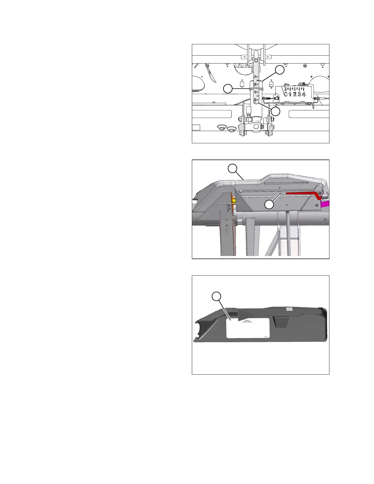
Figure 3.55: Center-Link
3. Adjust the center-link (A) so that indicator (B) is
between B and C on gauge (C).
4. Park combine on level ground and raise header until
cutterbar is 152–254 mm (6–10 in.) off the ground.
5. Shut down the engine, and remove the key from the
ignition.
6. If installed, move stabilizer/transport wheels so that
they are supported by header. Refer to Adjusting
Stabilizer / Slow Speed Transport Wheels, page 59.
Figure 3.56: Linkage Cover
7. Remove linkage cover (A) by removing bolt (B) and
rotating cover upward until inboard end can be lifted off.
Figure 3.57: Linkage Cover
NOTE:
Refer to the decal (A) inside each linkage cover.
OPERATION