EasyManua.ls Logo

Omron Sysmac NY-series User Manual

Omron Sysmac NY-series
744 pages
To Next Page IconTo Next Page
To Previous Page IconTo Previous Page
Page #103 background imageLoading...
Page #103 background image
Re-execution of Motion Control Instructions
Restarting with Enable in the Same Direction
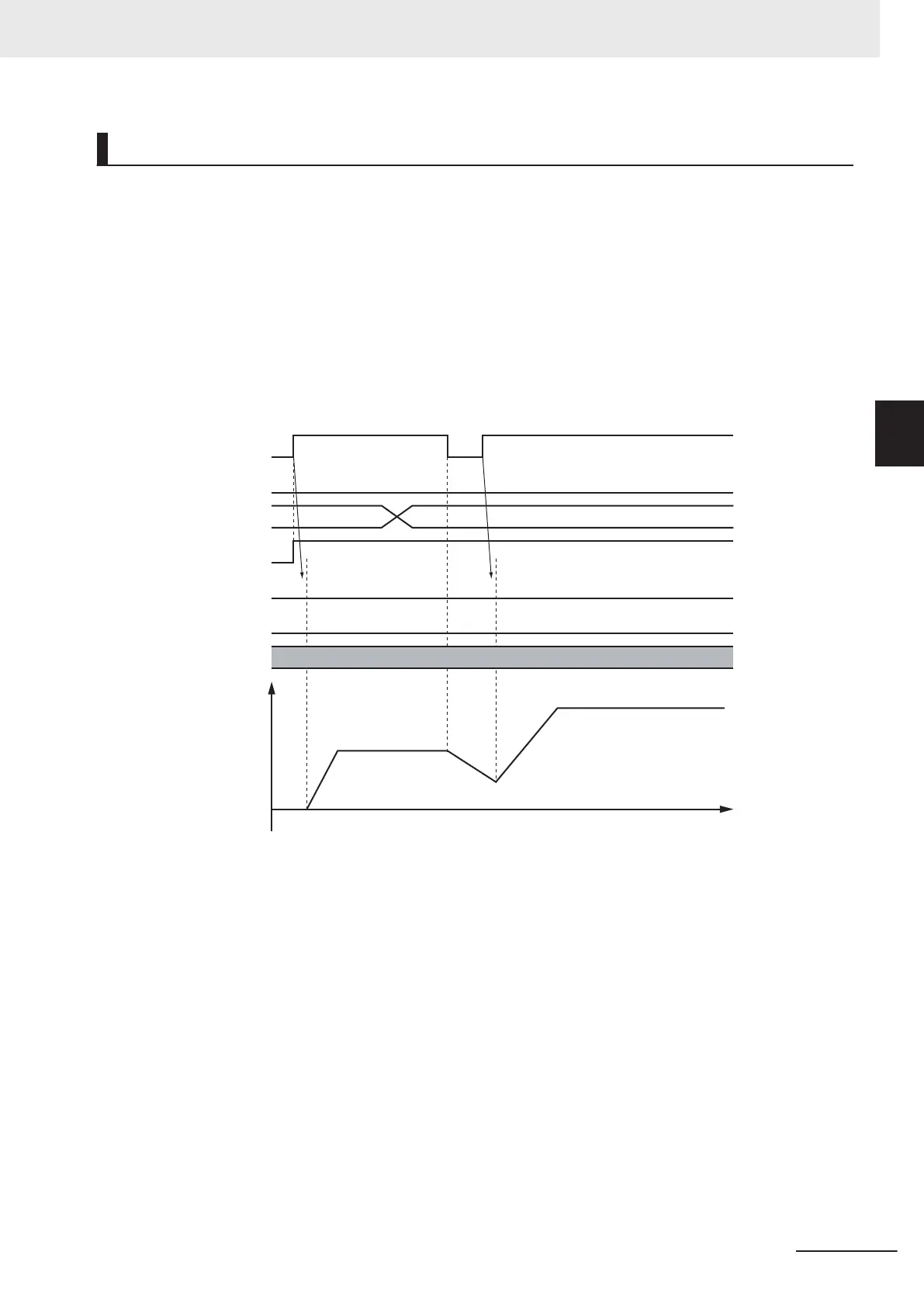
If you change PositiveEnable (Positive Direction Enable) or NegativeEnable (Negative Direction Ena-
ble) to TRUE when it is F
ALSE and the axis is decelerating, the axis will begin to accelerate towards
the target velocity.
If you change the Velocity (Target Velocity), Acceleration (Acceleration Rate), or Deceleration (Decel-
eration Rate) at this time, the new value of the input parameter is used in operation.
The axis is not stopped, and Busy (Executing) does not change to FALSE.
The following example shows operation when PositiveEnable (Positive Direction Enable) changes to
TRUE during deceleration.
Velocity
Time
Busy
NegativeEnable
CommandAborted
Error
ErrorID
PositiveEnable
Velocity
Velocity1 Velocity2
Velocity1
Velocity2
16#0000
Restarting with Enable in the Opposite Direction
If you change NegativeEnable (Negative Direction Enable) to TRUE when PositiveEnable (Positive Di-
rection Enable) is TRUE and the axis is jogging in the positive direction, the axis will reverse its direc-
tion and start jogging in the negative direction.
When this happens, you can jog the axis with the input variables for when NegativeEnable (Negative
Direction Enable) changes to TRUE. The input variables are V
elocity (Target Velocity), Acceleration
(Acceleration Rate), and Deceleration (Deceleration Rate).
The deceleration rate when the axis direction is reversed and the acceleration rate after it is reversed
follow the input variables for when NegativeEnable (Negative Direction Enable) changes to TRUE, re-
gardless of the Operation Selection at Reversing axis parameter.
When NegativeEnable (Negative Direction Enable) is TRUE and the axis is jogging in the negative di-
rection, the same operation occurs when PositiveEnable (Positive Direction Enable) changes to
TRUE.
3 Axis Command Instructions
3-15
NY-series Motion Control Instructions Reference Manual (W561)
MC_MoveJog
3
Function

Table of Contents

Question and Answer IconNeed help?

Do you have a question about the Omron Sysmac NY-series and is the answer not in the manual?

Omron Sysmac NY-series Specifications

General IconGeneral
CategoryControl Unit
Operating Temperature0 to 55 °C
Power Supply Voltage24 VDC
Power Supply24 VDC
Product SeriesNY-series
CPUIntel Atom or Intel Core i7
Programming LanguagesIEC 61131-3 (LD, FBD, ST, SFC)
Memory (Program)Up to 64 MB
Ethernet Ports2
EtherNet/IP Ports2 ports (built-in)
EtherCAT Master Ports1
EtherCATYes
Motion ControlSupported
SafetyYes
Built-in I/ONo
Relative Humidity10 to 90% (non-condensing)
Vibration Resistance5 to 8.4 Hz: 3.5 mm; 8.4 to 150 Hz: 9.8 m/s²
Shock Resistance147 m/s²
Power ConsumptionVaries by model
CertificationsCE, cULus, RCM, KC, EAC

Summary

Introduction to Motion Control Instructions

Variables and Instructions

Axis Command Instructions

MC_Power

Explains the MC_Power instruction for making a Servo Drive ready to operate.

MC_MoveJog

Explains the MC_MoveJog instruction for jogging an axis according to the specified target velocity.

MC_Home

Explains the MC_Home instruction for operating the motor to determine home.

MC_HomeWithParameter

Explains the MC_HomeWithParameter instruction for setting homing parameters and operating the motor to determine home.

MC_Move

Explains the MC_Move instruction for performing absolute positioning or relative positioning.

MC_MoveAbsolute

Explains the MC_MoveAbsolute instruction for moving the axis to a specified absolute target position.

MC_MoveRelative

Explains the MC_MoveRelative instruction for moving the axis the specified travel distance.

MC_MoveVelocity

Explains the MC_MoveVelocity instruction for performing velocity control.

MC_MoveZeroPosition

Explains the MC_MoveZeroPosition instruction for positioning to an absolute position of 0.

MC_Stop

Explains the MC_Stop instruction for decelerating an axis to a stop.

MC_ImmediateStop

Explains the MC_ImmediateStop instruction for stopping an axis immediately according to the specified stopping mode.

MC_CamIn

Explains the MC_CamIn instruction to start cam operation using a specified cam table.

MC_GearIn

Explains the MC_GearIn instruction to specify the gear ratio and start gear operation.

MC_GearInPos

Explains the MC_GearInPos instruction to perform electronic gear operation with specified gear ratio.

MC_MoveLink

Explains the MC_MoveLink instruction for positioning in sync with the specified master axis.

MC_TorqueControl

Explains the MC_TorqueControl instruction to control torque using the Torque Control Mode.

MC_SetTorqueLimit

Explains the MC_SetTorqueLimit instruction to limit torque output from the Servo Drive.

MC_TouchProbe

Explains the MC_TouchProbe instruction to record axis position when a trigger signal occurs.

MC_SyncMoveVelocity

Explains the MC_SyncMoveVelocity instruction for outputting target velocity in CSV Mode.

MC_SyncMoveAbsolute

Explains the MC_SyncMoveAbsolute instruction to cyclically output target positions.

MC_Reset

Explains the MC_Reset instruction to clear axis errors.

MC_DigitalCamSwitch

Explains the MC_DigitalCamSwitch instruction to turn a digital output ON or OFF based on axis position.

Axes Group Instructions

Common Command Instructions

Related product manuals