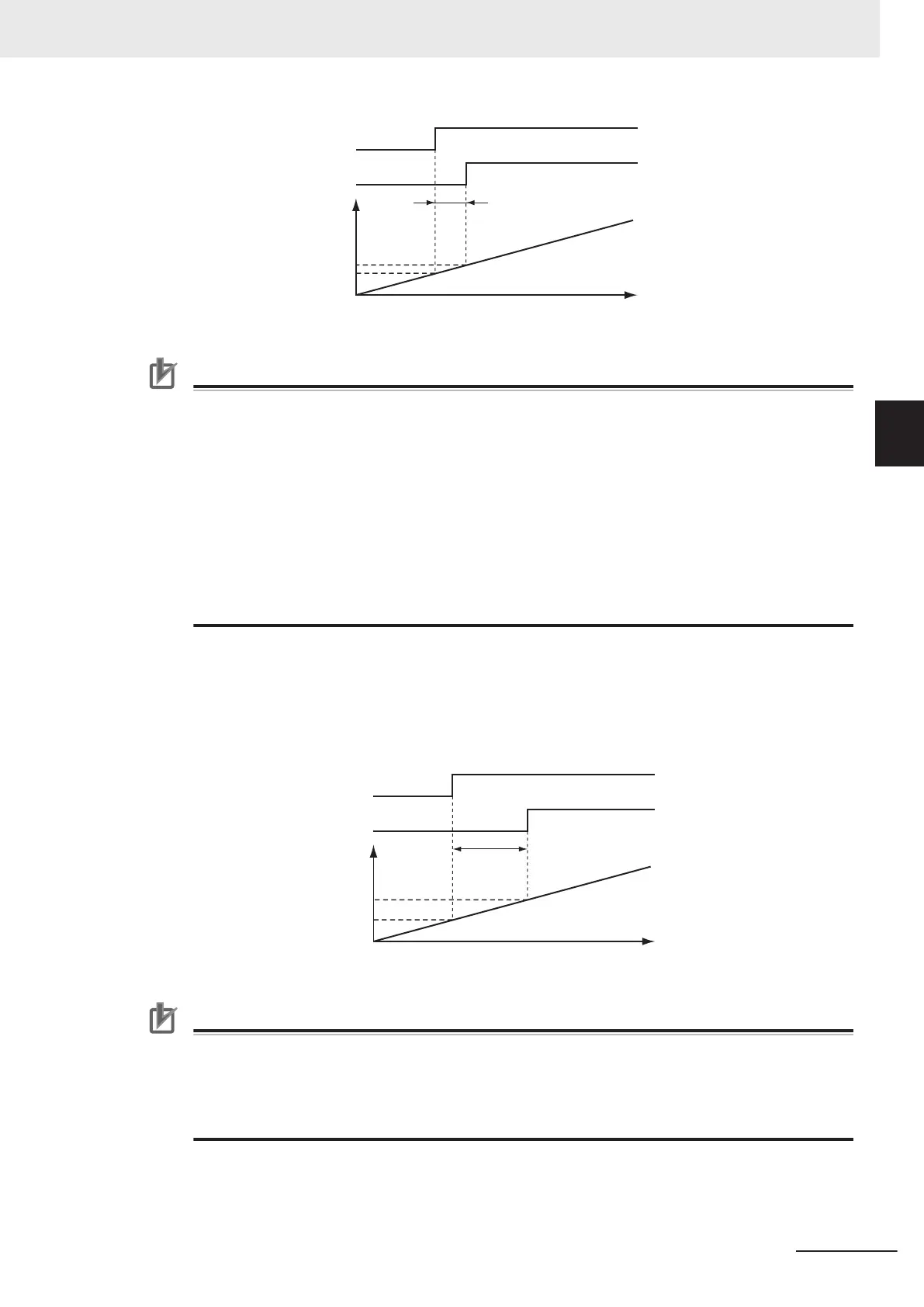
Time
Position
when trigger signal is input
Input filter delay
Position (latched p
osition)
Axis position
Trigger detection
Input signal to Servo Drive
Precautions for Correct Use
• When using Drive Mode, make sure that you connect the latch signal to the LatchID
that you
are going to use.
• The width of the latch signal depends on the performance of the Servo Drive or NX-series
Pulse Output Unit and other factors.
• You must map the following object data when the MC_MoveFeed (Interrupt Feeding) instruc-
tion is executed with InputDrive set to Drive Mode.
Touch probe function (60B8 hex), Touch probe status (60B9 hex), Touch probe pos1 pos val-
ue (60BA hex), and Touch probe pos2 pos value (60BC hex)
If even one of the required objects is not set, a Process Data Object Setting Missing error
(error code: 3461 hex) occurs.
For details on mapping object data, refer to 2-3 PDO Mapping on page 2-37 and to the NY-
series Industrial Panel PC / Industrial Box PC Motion Control User’s Manual (Cat. No. W559).
Controller Mode
•
You can specify a BOOL variable in the Controller Mode.
• Use TriggerVariable to specify the BOOL variable that you want to use as a trigger.
• The Controller Mode causes a longer delay compared to the Drive Mode. This is due to the I/O
refresh delay that occurs when the trigger input signal is updated in the BOOL variable.
Time
Input filter delay + I/O
refresh delay
Position when trigger signal is input
Position (latched p
osition)
Axis position
BOOL variable assigned to input signal
Input signal to Input Unit
Precautions for Correct Use
If you use Controller Mode, the latch is performed each task period. Therefore, the trigger vari-
able must remain TRUE for at least one task period.
Also, one task period is required between when the trigger variable changes to TRUE and the
MC Function Module processes the latch.
Here, the task period is the primary period.
LatchID
•
Specify which of the two to use with LatchID. You can use only one of the latches with any one axis.
• LatchID indicates latch circuit 1 and latch circuit 2 in the Servo Drive or NX-series Pulse Output Unit.
3 Axis Command Instructions
3-117
NY-series Motion Control Instructions Reference Manual (W561)
MC_MoveFeed
3
Function