Relative amounts are applied to the phase and displacements in the cam table so that the start point is
zeroed. The absolute position of each axis at each phase is the relative value from the absolute posi-
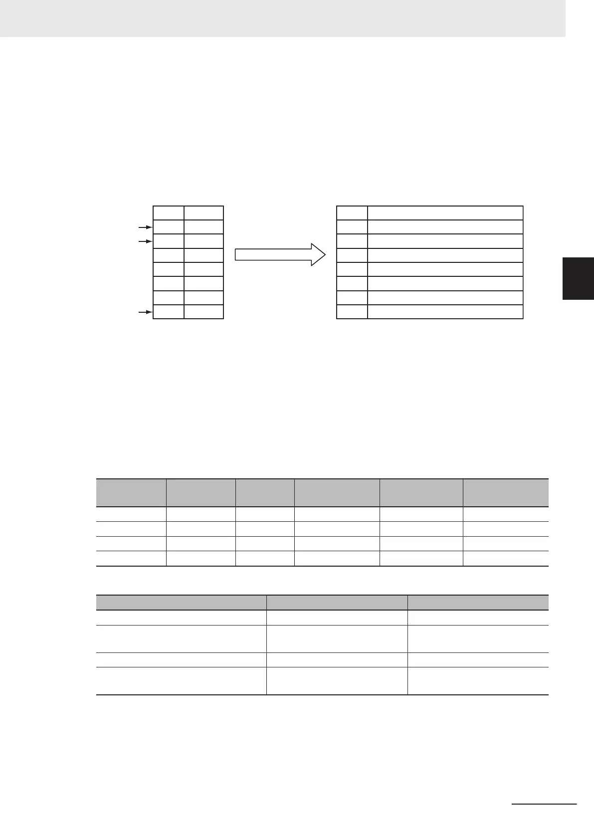
tion of the axis at the start point of the cam table. For example, if the Count Mode of the master axis is
0° to 360° in Rotary Mode, the StartPosition (Cam T
able Start Position) is 60. The absolute position of
the master axis is the phase added to the StartPosition (Cam Table Start Position), as shown in the
following cam table. The absolute position of the slave axis is the displacement from the cam table
added to the absolute position of the slave axis at the start point of the cam table.
0 0
60 200
StartPositio
n=60
120 100
180 300
240 100
300 200
360 0
60
60
120
180
240
300
360
Cam Table
Phase
Displacement
Absolute Position of Axes
Master axis
Slave axis
0 + Absolute position of slave axis at start point of cam table
200 + Absolute position of slave axis at start point of cam table
100 + Absolute position of slave axis at start point of cam table
300 + Absolute position of slave axis at start point of cam table
100 + Absolute position of slave axis at start point of cam table
200 + Absolute position of slave axis at start point of cam table
0 + Absolute position of slave axis at start point of cam table
Start point
Cam data
End point
When the MasterStartDistance (Master Following Distance) is then passed, the cam operation of the
slave axis starts and the InSync output variable changes to TRUE.
The MasterStartDistance
(Master Following Distance) is specified either as an absolute position, or as
a relative distance from the StartPosition (Cam Table Start Position). Set whether to specify using an
absolute position or relative position with StartMode.
Example 1: Differences in Slave Axis Operation for Differences in MasterStartDistance
In this example, the same cam table and same master axis are used.
The cam table settings are given in the following table.
Master axis Slave axis Cam curve
Connecting ve-
locity
Connecting ac-
celeration
Phase pitch
0.000 0.000 --- --- --- ---
80.000 80.000 Straight line 360.000 0.000 0.010
120.000 200.000 Straight line 1080.000 0.000 0.010
360.000 360.000 Straight line 240.000 0.000 0.010
The conditions for starting cam operation are given in the following table.
Input variable Condition 1 Condition 2
Periodic (Periodic Mode) TRUE: Periodic TRUE: Periodic
StartMode _mcRelativePosition (Relative
Position)
_mcRelativePosition (Relative
Position)
StartPosition (Cam Table Start Position) 0 0
MasterStartDistance (Master Following
Distance)
0 80
For condition 1, the InCam (Cam Motion) and InSync output variables both change to TRUE and the
slave axis starts cam operation when the master axis passes 0°.
For condition 2, the InCam (Cam Motion) changes to TRUE when the master axis passes 0°. Then,
the InSync output variable changes to TRUE and the slave axis starts cam operation when the master
3 Axis Command Instructions
3-181
NY-series Motion Control Instructions Reference Manual (W561)
MC_CamIn
3
Function