EasyManua.ls Logo

Omron Sysmac NY-series User Manual

Omron Sysmac NY-series
744 pages
To Next Page IconTo Next Page
To Previous Page IconTo Previous Page
Page #513 background imageLoading...
Page #513 background image
Precautions for Safe Use
Always use the axis at a constant velocity for the MC_DigitalCamSwitch instruction.
If you set the Count Mode to Rotary Mode, the following operation will occur if you use
OnCompensation or OffCompensation
and the axis velocity changes abruptly.
If the value of OnCompensation or OffCompensation is equivalent to the time for half a rota-
tion or more, InOperation will be FALSE.
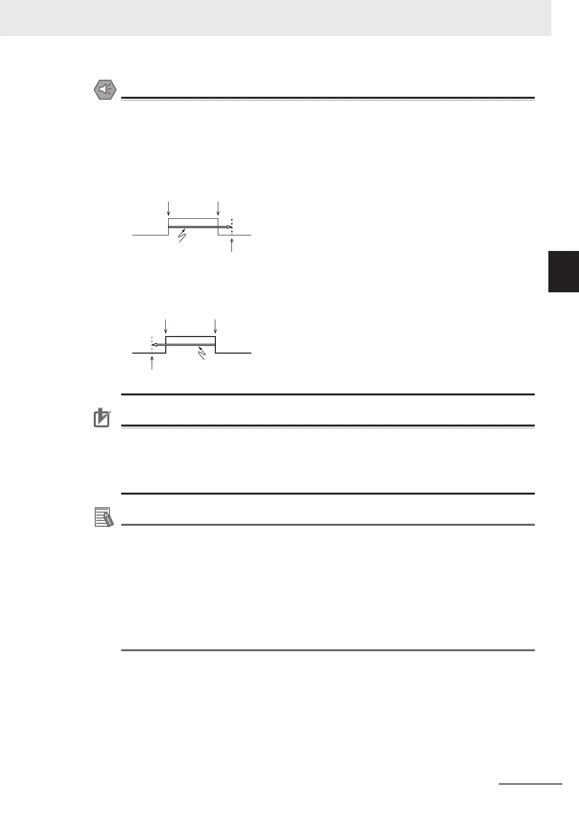
If the value of OnCompensation results in exceeding LastOnPosition, the output timing will be
unstable.
FirstOnPosition LastOnPosition
OnCompensation
FirstOnPosition after compensation
If the value of OffCompensation results in exceeding FirstOnPosition, the output timing will be
unstable.
FirstOnPosition LastOnPosition
OffCo
mpensation
LastOnPosition after compensation
Precautions for Correct Use
If you set the Count Mode to Rotary Mode and use OnCompensation or OffCompensation, set
the parameters so that the relationship between FirstOnPosition and LastOnPosition is not re-
versed.
The output timing will be unstable.
Refer to "Precautions for Safe Use", above, for operation information.
Additional Information
If the Count Mode is set to Rotary Mode, the valid range is T#-1s to T#1s, but the following
restrictions also apply to the setting.
Set the value within a range that does not exceed the time for half a rotation of the axis.
For example, for rotation at 500 r/min, the time for one rotation is 120 ms. The time is for half
a rotation, so set OnCompensation (ON Time Compensation) and OffCompensation (OFF
Time Compensation) to between −60 and 60 ms.
If a value is set that exceeds the time for half a rotation of the axis, InOperation will be FALSE
and EnableOut will be FALSE. Always check the status of InOperation during application.
If a value within the correct range is restored when InOperation is FALSE, InOperation will
change to TRUE.
The following figure shows the operation when OnCompensation (ON T
ime Compensation) is set to
T#5ms and OffCompensation (OFF Time Compensation) is set to T#10ms for the Setting Example
given on page 3-422.
3 Axis Command Instructions
3-425
NY-series Motion Control Instructions Reference Manual (W561)
MC_DigitalCamSwitch
3
Function

Table of Contents

Question and Answer IconNeed help?

Do you have a question about the Omron Sysmac NY-series and is the answer not in the manual?

Omron Sysmac NY-series Specifications

General IconGeneral
CategoryControl Unit
Operating Temperature0 to 55 °C
Power Supply Voltage24 VDC
Power Supply24 VDC
Product SeriesNY-series
CPUIntel Atom or Intel Core i7
Programming LanguagesIEC 61131-3 (LD, FBD, ST, SFC)
Memory (Program)Up to 64 MB
Ethernet Ports2
EtherNet/IP Ports2 ports (built-in)
EtherCAT Master Ports1
EtherCATYes
Motion ControlSupported
SafetyYes
Built-in I/ONo
Relative Humidity10 to 90% (non-condensing)
Vibration Resistance5 to 8.4 Hz: 3.5 mm; 8.4 to 150 Hz: 9.8 m/s²
Shock Resistance147 m/s²
Power ConsumptionVaries by model
CertificationsCE, cULus, RCM, KC, EAC

Summary

Introduction to Motion Control Instructions

Variables and Instructions

Axis Command Instructions

MC_Power

Explains the MC_Power instruction for making a Servo Drive ready to operate.

MC_MoveJog

Explains the MC_MoveJog instruction for jogging an axis according to the specified target velocity.

MC_Home

Explains the MC_Home instruction for operating the motor to determine home.

MC_HomeWithParameter

Explains the MC_HomeWithParameter instruction for setting homing parameters and operating the motor to determine home.

MC_Move

Explains the MC_Move instruction for performing absolute positioning or relative positioning.

MC_MoveAbsolute

Explains the MC_MoveAbsolute instruction for moving the axis to a specified absolute target position.

MC_MoveRelative

Explains the MC_MoveRelative instruction for moving the axis the specified travel distance.

MC_MoveVelocity

Explains the MC_MoveVelocity instruction for performing velocity control.

MC_MoveZeroPosition

Explains the MC_MoveZeroPosition instruction for positioning to an absolute position of 0.

MC_Stop

Explains the MC_Stop instruction for decelerating an axis to a stop.

MC_ImmediateStop

Explains the MC_ImmediateStop instruction for stopping an axis immediately according to the specified stopping mode.

MC_CamIn

Explains the MC_CamIn instruction to start cam operation using a specified cam table.

MC_GearIn

Explains the MC_GearIn instruction to specify the gear ratio and start gear operation.

MC_GearInPos

Explains the MC_GearInPos instruction to perform electronic gear operation with specified gear ratio.

MC_MoveLink

Explains the MC_MoveLink instruction for positioning in sync with the specified master axis.

MC_TorqueControl

Explains the MC_TorqueControl instruction to control torque using the Torque Control Mode.

MC_SetTorqueLimit

Explains the MC_SetTorqueLimit instruction to limit torque output from the Servo Drive.

MC_TouchProbe

Explains the MC_TouchProbe instruction to record axis position when a trigger signal occurs.

MC_SyncMoveVelocity

Explains the MC_SyncMoveVelocity instruction for outputting target velocity in CSV Mode.

MC_SyncMoveAbsolute

Explains the MC_SyncMoveAbsolute instruction to cyclically output target positions.

MC_Reset

Explains the MC_Reset instruction to clear axis errors.

MC_DigitalCamSwitch

Explains the MC_DigitalCamSwitch instruction to turn a digital output ON or OFF based on axis position.

Axes Group Instructions

Common Command Instructions

Related product manuals