Cam Property Structure (_sMC_CAM_PROPERTY Data Type)
The cam property structure (_sMC_CAM_PROPERTY) is used to specify the properties. Some of the
members correspond to the cam table properties that are set with the Cam Editor of the Sysmac Stu-
dio.
This cam property structure is used for the CamProperty (Cam Properties) in-out variable that is speci-
fied for this instruction.
The members of the cam property structure are described in the following table.
Name Meaning Data type Valid range Description
InitVel Initial Veloci-
ty
REAL
Negative number
*1
, positive
number
*1
, or 0
Set the velocity when operation is started
at the start node (phase = 0 and displace-
ment = 0).
The initial velocity is valid when the curve
shape for the next cam node after the
start node is set to polynomic 3 or poly-
nomic 5.
The unit is command units/s.
InitAcc Initial Accel-
eration
REAL
Negative number
*1
, positive
number
*1
, or 0
Set the acceleration when operation is
started at the start node (phase = 0 and
displacement = 0).
The initial acceleration is valid when the
curve shape for the next cam node after
the start node is set to polynomic 5.
The unit is command units/s
2
.
CycleTime Cycle Time REAL
Positive number
*1
Specify the time for one cam operation
cycle.
The unit is seconds.
*1. Specify a value that has an absolute value of 0.001 or greater. The value is rounded to the forth decimal place.
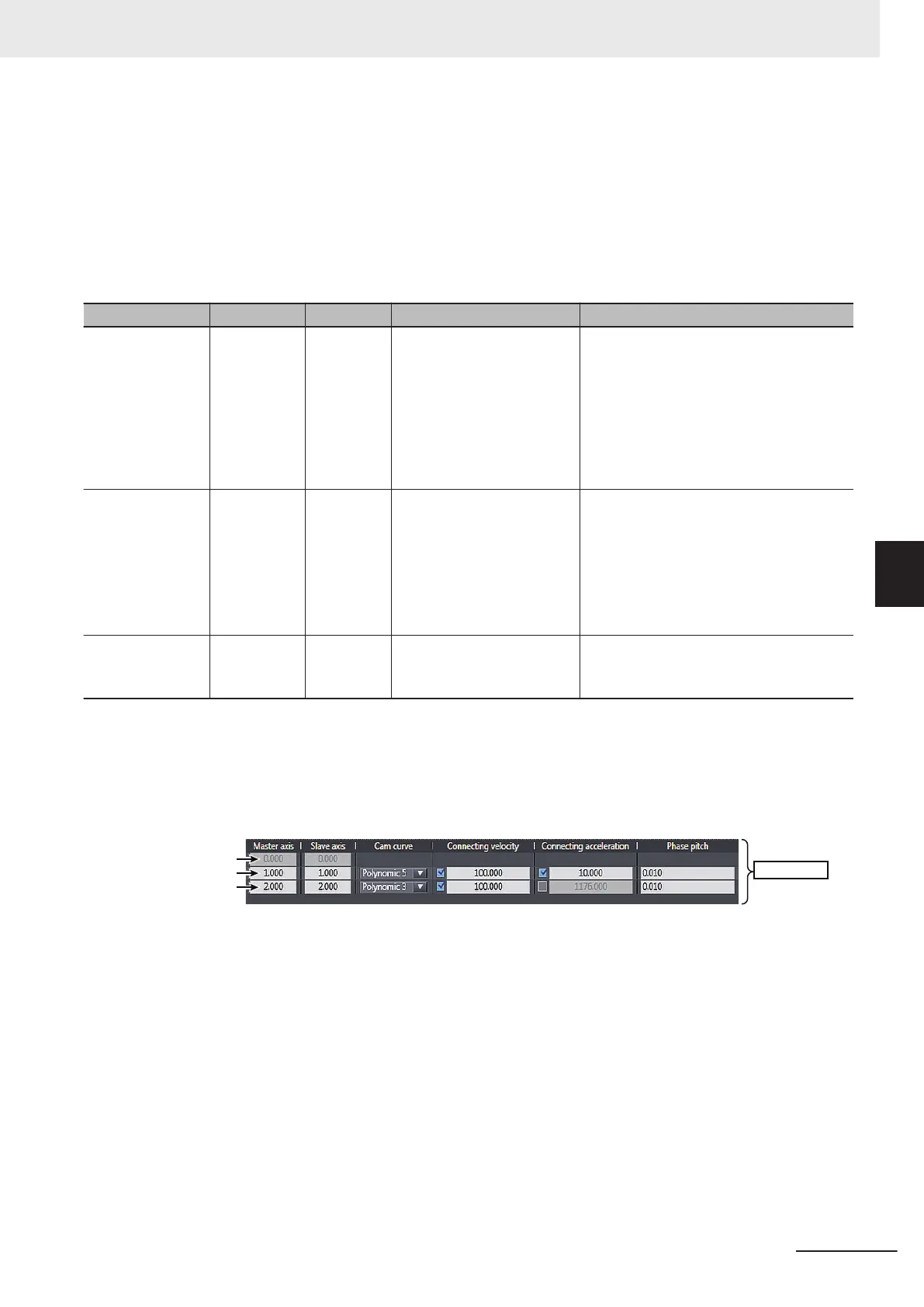
Cam Node Structure (_sMC_CAM_NODE Data Type)
The cam node structure (_sMC_CAM_NODE) is used to define the curve shapes. Some of the mem-
bers correspond to the Cam Nodes items that are set with the Cam Editor of the Sysmac Studio.
Cam nodes
CamNodes[0]
Start node
CamNodes[1]
This cam node structure is used for the CamNodes in-out variable that is specified for this instruction.
An element in the cam node array variable is called a node point. The number of elements in the array
variable must be equal to or greater than the number of node points that is set.
The node point that is the start point of the cam profile curve (phase = 0, displacement = 0) is called
the start node. Except for the start node, the node points in the array variable are in the order of the
element numbers.
If you specify a positive number that is 0.001 or higher for Phase
(Master Axis Phase), the node is
valid. If you specify 0, that node and all following nodes are invalid. However, if you set Phase (Master
Axis Phase) for element number 0 to 0, an error occurs.
The following example shows five valid nodes and 10 elements in an array variable.
5 Common Command Instructions
5-23
NY-series Motion Control Instructions Reference Manual (W561)
MC_GenerateCamTable
5
Function