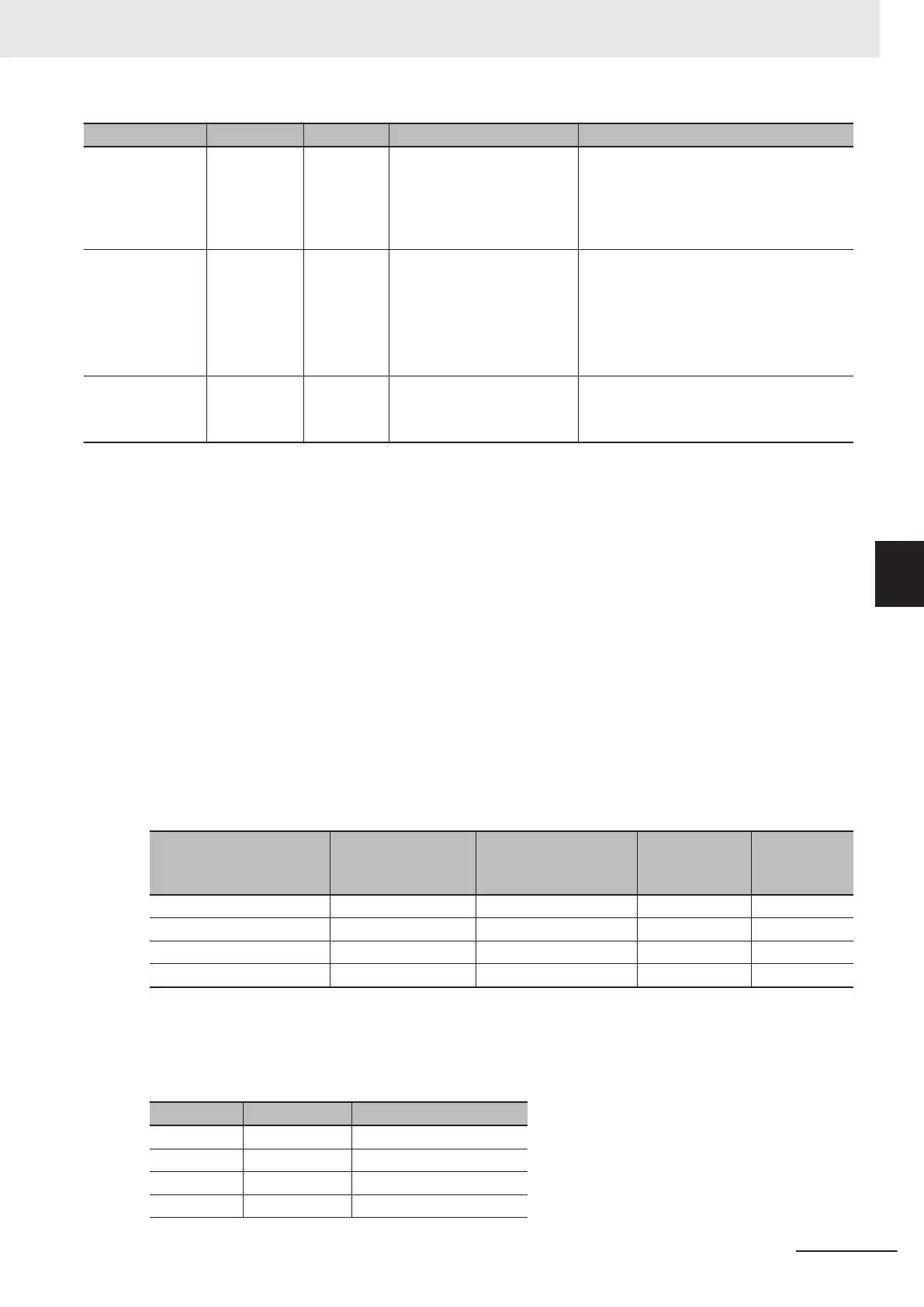
Name Meaning Data type Valid range Description
ConnectingAc-
cEnable
Connecting
Acceleration
Enable
BOOL TRUE or FALSE Set to TRUE to enable the specified con-
necting acceleration when the specified
curve shape is polynomic 5.
Set to F
ALSE to disable the connecting
acceleration.
ConnectingAcc Connecting
Acceleration
REAL
Negative number
*1
, positive
number
*1
, or 0
If the specified curve shape is polynomic
5, you can specify the acceleration of the
connecting section to the next curve.
Use this setting for smooth connections
between curves.
The unit is command units/s
2
.
PhasePitch Phase Pitch REAL
Positive number
*1
The phase between node points is divided
by the specified pitch width.
*4
The unit is command units.
*1. Specify a value that has an absolute value of 0.001 or greater. The value is rounded to the forth decimal place.
*2. Phase (Master Axis Phase) and Distance (Slave Axis Displacement) are ef
fective to seven digits. If you enter more
than seven digits, the digits that are not effective are truncated. If a truncated value is the same as the value of another
value in Phase (Master Axis Phase), a Cam Node Master Axis Phase Not in Ascending Order error (error code: 5740
hex) occurs. Enter values in ascending order for seven digits or less.
*3. If you specify a straight line with constant displacement, Distance (Slave Axis Displacement) is disabled and the value
that is specified for the previous node point is used for processing. If the array element number is 0 and you specify a
straight line with constant displacement, Distance (Slave Axis Displacement) is treated as 0.
*4. Make the settings so that the total of all cam data that is created for each node point is 65,535 or less.
Example of Creating a Cam Table
This section provides an example of creating a cam table with this instruction.
There are four elements in the array variable that is specified for CamNodes. _mcStraightLine
(Straight Line) is specified for Curve (Curve Shape). ConnectingV
el (Connecting Velocity) and
ConnectingAcc (Connecting Acceleration) are disabled, as are InitVel (Initial Velocity) and InitAcc (Ini-
tial Acceleration) in CamProperty (Cam Properties), so they are not given here. The values of Phase
(Master Axis Phase) and Distance (Slave Axis Displacement) are given in the following table.
Element number in
CamNodes array variable
Phase
(Master Axis
Phase)
Distance
(Slave Axis Displace-
ment)
Curve
(Curve Shape)
PhasePitch
(Phase Pitch)
0 180.000 180.000 _mcStraightLine 0.100
1 360.000 0.000 _mcStraightLine 0.100
2 0.00 --- --- ---
3 --- --- --- ---
This example uses a cam data variable with 4,000 elements that was created in advance with the
Cam Editor of the Sysmac Studio. All phases and displacements are set to “undefined.”
The cam data variable for the cam table is as shown in the following table before the instruction is exe-
cuted.
Element No. Phase (Phase) Distance (Displacement)
0 (Undefined) (Undefined)
1 (Undefined) (Undefined)
...
1799 (Undefined) (Undefined)
5 Common Command Instructions
5-25
NY-series Motion Control Instructions Reference Manual (W561)
MC_GenerateCamTable
5
Function