Element No. Phase (Phase) Distance (Displacement)
1800 (Undefined) (Undefined)
1801 (Undefined) (Undefined)
...
3599 (Undefined) (Undefined)
3600 (Undefined) (Undefined)
3601 (Undefined) (Undefined)
...
3999 (Undefined) (Undefined)
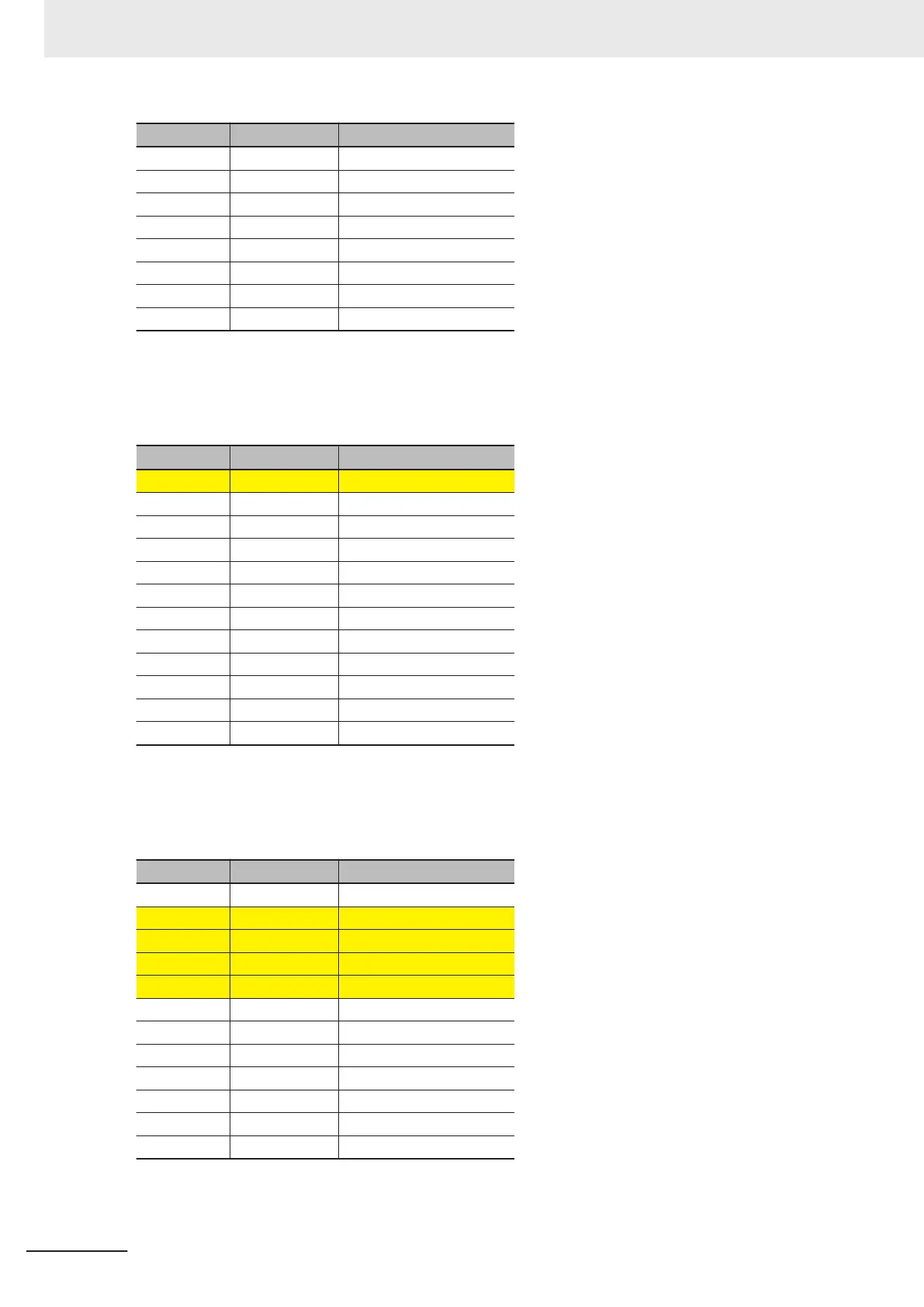
Next, we describe the sequence of changes that occur in the cam data variable as the instruction is
executed. The locations that changed are showed by filled backgrounds.
When the MC_GenerateCamT
able instruction is executed, 0 is written to the phase and displacement
of element 0 of the cam data variable.
Element No. Phase (Phase) Distance (Displacement)
0 0.0 0.0
1 (Undefined) (Undefined)
...
1799 (Undefined) (Undefined)
1800 (Undefined) (Undefined)
1801 (Undefined) (Undefined)
...
3599 (Undefined) (Undefined)
3600 (Undefined) (Undefined)
3601 (Undefined) (Undefined)
...
3999 (Undefined) (Undefined)
Next, the number of cam data and the phase and displacement for each cam data are calculated from
the start node to the node point according to the specified values for element 0 in CamNodes. The
number of cam data calculates as 1,800, so the phases and displacements of element 1 to 1800 are
written to the cam data variable.
Element No. Phase (Phase) Distance (Displacement)
0 0.0 0.0
1 0.1 0.1
...
1799 179.9 179.9
1800 180.0 180.0
1801 (Undefined) (Undefined)
...
3599 (Undefined) (Undefined)
3600 (Undefined) (Undefined)
3601 (Undefined) (Undefined)
...
3999 (Undefined) (Undefined)
In the same way, the number of cam data and the phase and displacement for each cam data are cal-
culated between node points according to the specified values for element 1 in CamNodes. The
5 Common Command Instructions
5-26
NY-series Motion Control Instructions Reference Manual (W561)