Chapter 6 Running Your Library
Understanding Location Coordinates
Scalar i2000 User’s Guide 377
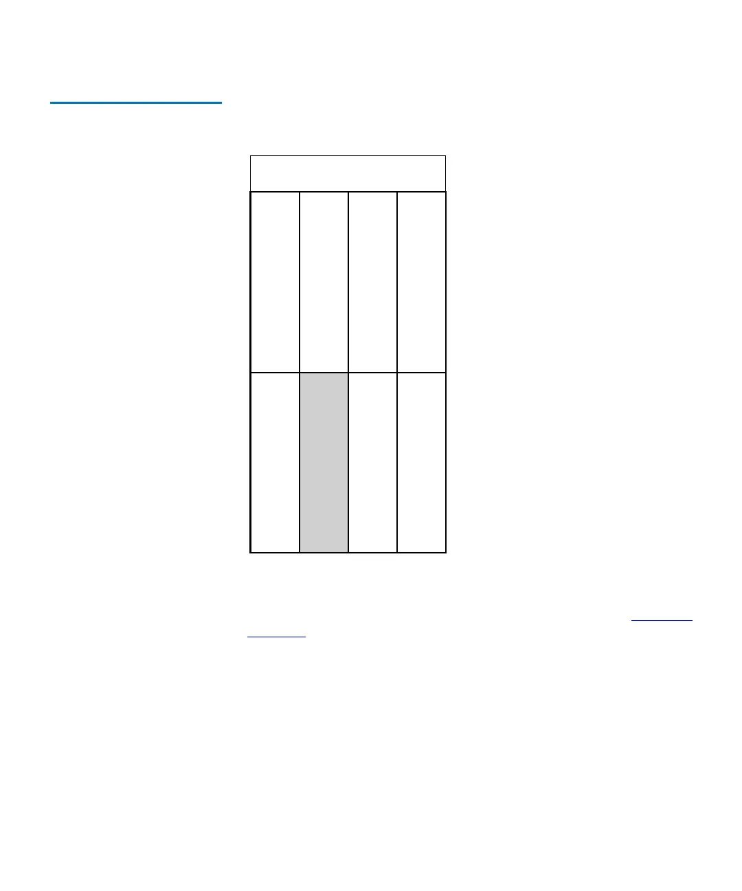
Figure 46 I/O Management
Unit Blade Numbering
The definitions for aisle, module, and rack are the same for I/O blades as
they are for other library components. For more information, see
Cartridge
Locations on page 366.
The key to interpreting the last two blade location coordinates follows:
• Cluster — the cluster designation for the I/O management unit is
always 1.
• Bay — there are eight bays in the I/O management unit. If you look
at the I/O management unit from the back of a library module, bay 1
is the bay on the lower left. Bay 1 is not populated. Bay 2 always
contains a management control blade (MCB). No I/O blades can be
installed in bays 1 or 2. Bays 3 through 5 can contain I/O blades.
bay 1 (not used)
bay 3 (first FC I/O blade)
bay 5 (third FC I/O blade)
bay 4 (second FC I/O blade)
bay 6 (not used)
bay 8 (not used)
fan
bay 7 (not used)
(1,1,1,1,3) (1,1,1,1,4)
(1,1,1,1,5) (1,1,1,1,6)
(1,1,1,1,7) (1,1,1,1,8)
bay 2 (CMB)
(1,1,1,1,2)