R&S
®
ZVA / R&S
®
ZVB / R&S
®
ZVT GUI Reference
Trace Menu
Operating Manual 1145.1084.12 – 30 121
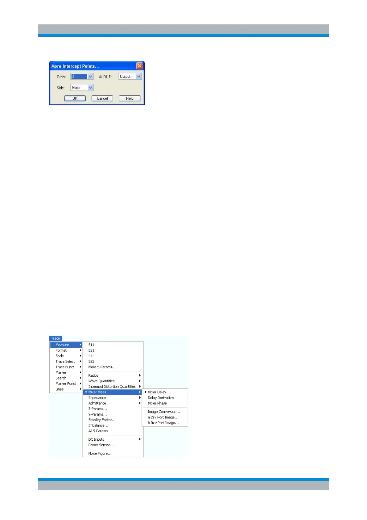
The controls in the dialog define the order of the intercept point, measured at the DUT input or output, and
the position of the intercept point relative to the lower and upper tones.
The Lower intercept points are calculated using the intermodulation suppression IMk
rel
measured
at frequencies below the lower tone (above the lower tone for an inverted frequency conversion,
where IF=LO-RF). Please note that IMk
rel
is always measured at the DUT output.
The Upper intercept points are calculated using the intermodulation suppression IMk
rel
measured
at frequencies above the lower tone (below the lower tone for an inverted frequency conversion,
where IF=LO-RF). Please note that IMk
rel
is always measured at the DUT output.
Major denotes the lower or upper intercept point, whichever is smaller. The Major intercept point
reveals the worst-case performance of the DUT.
CALCulate<Ch>:PARameter:MEASure "<Trace_Name>", "MIXDLY" ...
Create new trace and select name and measurement parameter:
CALCulate<Ch>:PARameter:SDEFine "<Trace_Name>", "MIXDLY" ...
Mixer Meas
The Mixer Meas submenu provides the results of the mixer delay measurement and results that the
analyzer acquires at the RF image frequency:
Mixer delay measurements require option R&S ZVA-K9. The results are available as soon as the
measurement has been properly configured using the Define Mixer Delay Measurement without
LO Access wizard (Channel – Mode – Mixer Delay Meas – Define Mixer Delay Meas).
To obtain the RF image traces, a scalar mixer measurement must be active. When an image trace
is selected, the analyzer opens a dialog to specify the detector settings. An error message is
displayed if the image frequency range RF' exceeds the analyzer's frequency range.