R&S
®
ZVA / R&S
®
ZVB / R&S
®
ZVT GUI Reference
Trace Menu
Operating Manual 1145.1084.12 – 30 133
PAE... opens a dialog to select and configure the PAE measurement.
All DC and PAE measurements use the input connectors DC MEAS at the rear of the instrument. The
measurement results are real-valued and displayed as a function of sweep variable (frequency, internal
source power, time). The measurements can be performed in parallel to all RF measurements.
Exception: The PAE is not available in true differential mode.
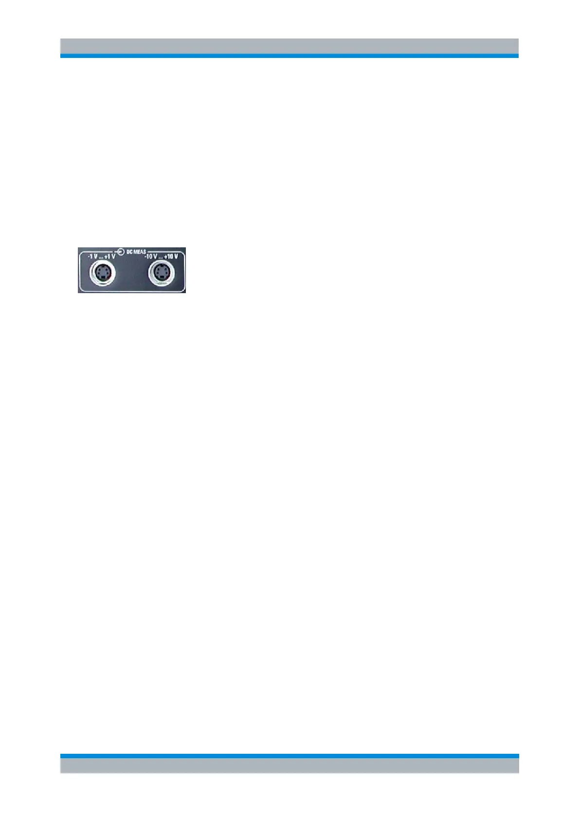
DC MEAS –1 V...+1 V, DC MEAS –10 V...+10 V
Select the DC voltages between pins 6 and 8 of the DC MEAS input connectors as measured quantities.
The input connectors are located at the rear panel of the instrument.
The two DC inputs cover different input voltage ranges; see data sheet or rear panel labelling.
The left input connector DC MEAS –1 V...+1 V provides the most accurate measurement for
smaller voltages but has a restricted input voltage range.
The right input connector DC MEAS –10 V...+10 V can be used for larger voltages.
CALCulate<Ch>:PARameter:MEASure "<Trace_Name>", "DC+1V" |
"DC+10V"
Create new trace and select name and measurement parameter:
CALCulate<Ch>:PARameter:SDEFine "<Trace_Name>", "DC+1V" |
"DC+10V"
PAE...
Opens a dialog to select the Power Added Efficiency (PAE) of an active 2-port device as measured
quantity and to define the parameters for the PAE measurement.