R&S
®
ZVA / R&S
®
ZVB / R&S
®
ZVT GUI Reference
Trace Menu
Operating Manual 1145.1084.12 – 30 173
maximum frequency of the analyzer, then an error message is displayed, and another harmonic grid
algorithm must be used.
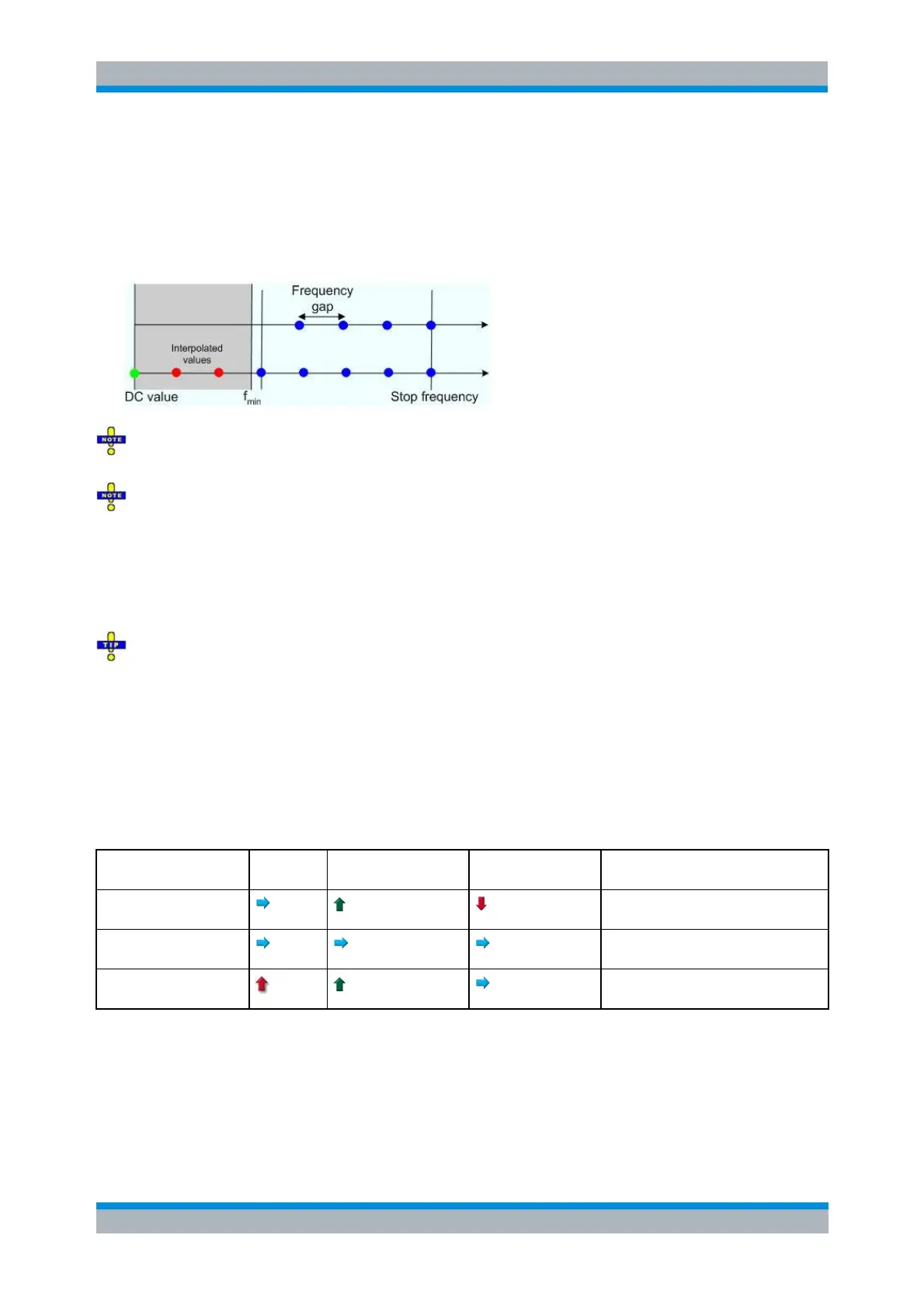
Keep Stop Frequency and Approximate Frequency Gap means that the stop frequency is
maintained and the number of sweep points is increased until the range between f
min
and the stop
frequency is filled. The frequency gap is approximately maintained.
The figures above are schematic and do not comply with the conditions placed on the number of
sweep points and interpolated/extrapolated values.
The harmonic grids can not be calculated for any set of sweep points. If the minimum number of
sweep points is smaller than 6, then the interpolation/extrapolation algorithm for additional sweep points
will not work. The same is true if the number of sweep points or stop frequency exceeds the upper limit.
Besides, the ratio between the sweep range and the interpolation range between f = 0 and f = f
min
must be
large enough to ensure accurate results.
If the sweep range for the harmonic grid exceeds the frequency range of the current system error
correction, a warning is displayed.
Finding the appropriate algorithm
The three types of harmonic grids have different advantages and drawbacks. Note that for a bandpass
transformation the grid parameters have the following effect:
A wider sweep range (i.e. a larger bandwidth) increases the time domain resolution.
A smaller frequency gap extends the unambiguous range.
A larger number of points increases the sweep time.
With default analyzer settings, the difference between the grid types are small. The following table helps
you find the appropriate grid.
Stop freq. and no. of
points
Freq. gap and no. of
points
Stop frequency beyond upper
frequency limit
Stop freq. and approx.
freq. gap
Number of sweep points beyond limit
CALCulate<Chn>:TRANsform:TIME:LPASs KFSTop | KDFRequency |
KSDFrequency