R&S
®
ZVA / R&S
®
ZVB / R&S
®
ZVT GUI Reference
Channel Menu
Operating Manual 1145.1084.12 – 30 251
Control Loop Parameters define the tuning coefficients of the Proportional-Integral (PI) controller
the analyzer uses as a feedback controller for ALC.
By default the parameters are automatically selected (Coefficients=Auto). With automatic
selection of the ALC Path IF Bandwidth this is the only option. If ALC Path IF Bandwidth is set
manually, it is also possible to vary the coefficients manually; see background information below.
Settling Tolerance defines the maximum variation of the source signal level after the ALC has
settled.
The settling tolerance has an impact on the ALC Path IF Bandwidth in Auto mode: other things
being equal, the smaller the Settling Tolerance the smaller the auto-selected filter bandwidth.
Activate Low Phase Noise Mode for ALC ensures that Low Phase Noise Mode is activated
whenever ALC is used on a port.
Control Loop Parameters
Proportional-Integral (PI) controllers provide two control parameters:
The Proportional Gain Kr controls the change of the controller output in response to the current
error value. If the value is too high, the ALC may become unstable. If it is too low, the ALC may
not respond sufficiently to errors and become too slow.
The Integration Time Ki controls the change of the controller output based on the integral of the
error over time. If the value is high, the ALC becomes slower. If it is too low, the ALC may
overshoot and thus become unstable.
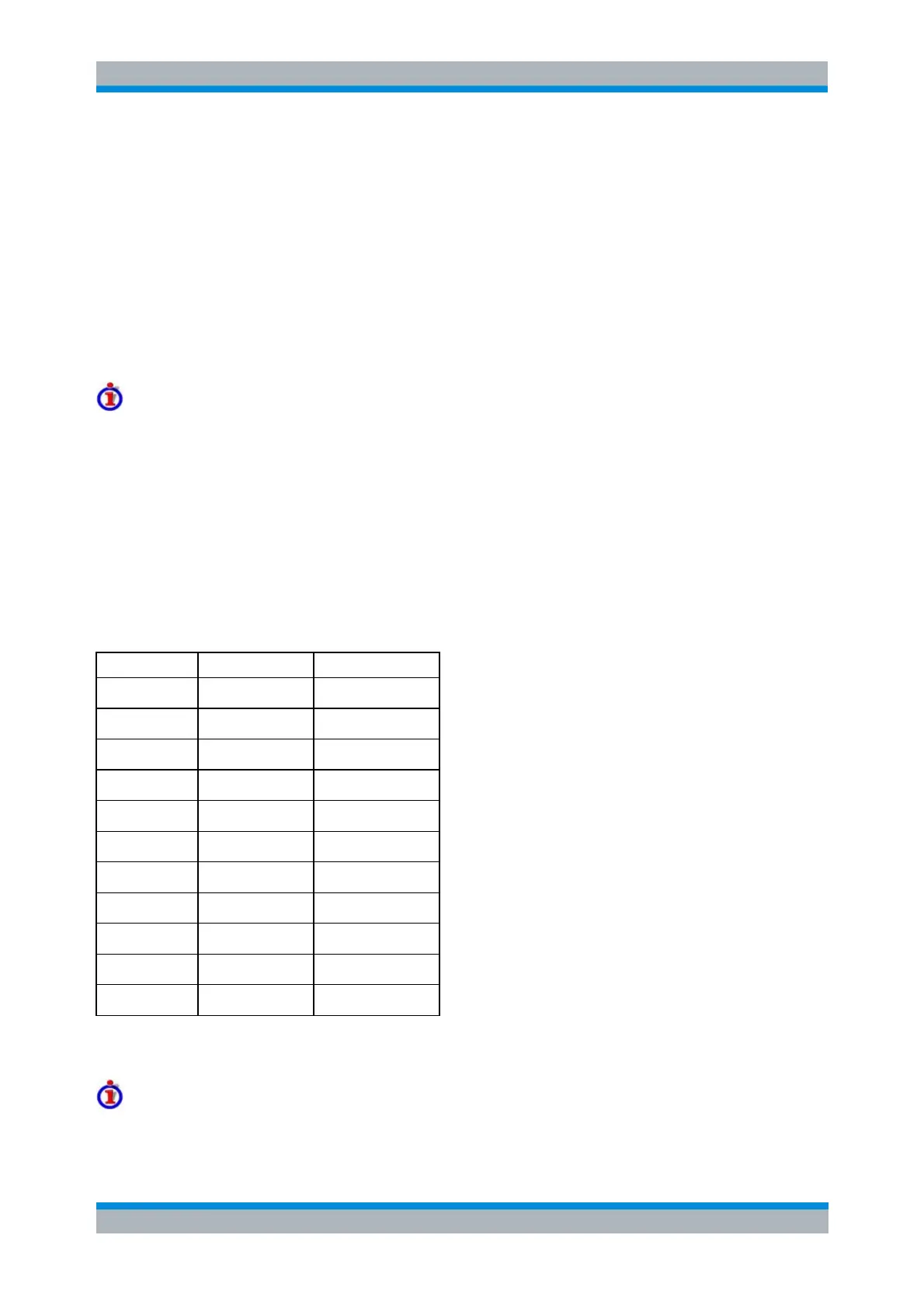
The proportional and integration terms are summed to calculate the controller output, so there is a tradeoff
between the two terms. With automatic ALC parameter setting, the control parameters are determined by
the selected ALC bandwidth as shown in the following table.
For some test scenarios, an adjustment of the ALC parameters (loop tuning) can improve the stability and
speed of the ALC.
Tooltips in the dialog
Please perform a source power calibration for all ALC ports.