R&S
®
ZVA / R&S
®
ZVB / R&S
®
ZVT GUI Reference
Channel Menu
Operating Manual 1145.1084.12 – 30 266
Pulse Profile
Pulse Profile measurements are performed at constant receiver frequency and stimulus power; see
background information on pulse profile mode. Pulsed measurements require a trigger signal that is
synchronized to the analyzed pulses. Besides all settings are accessible in the Define Pulse Profile dialog.
[SENSe<Ch>:]SWEep:TYPE PULSe
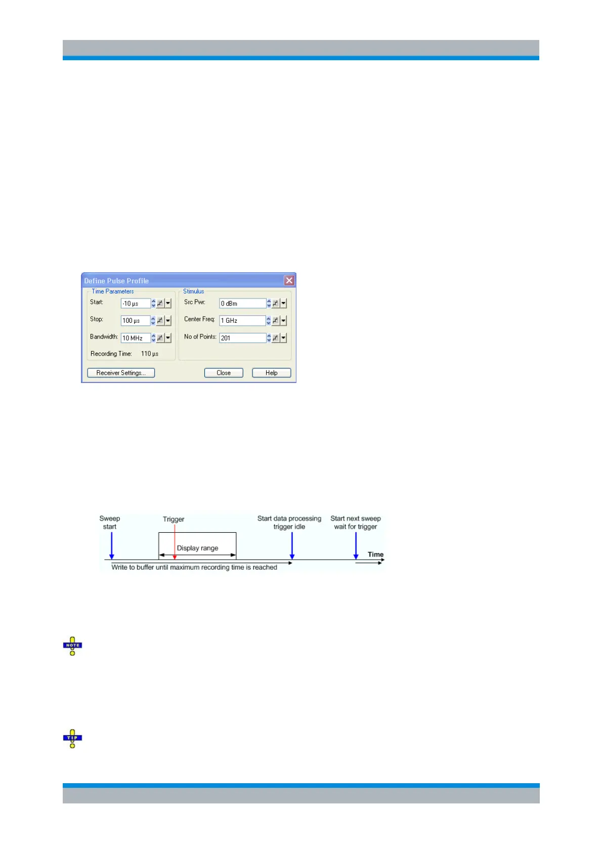
Define Pulse Profile...
Opens a dialog to configure the time parameters, the stimulus signal settings, and the receiver settings for
pulsed measurements.
The Time Parameters define the displayed time range and the IF bandwidth:
Start and Stop define the start and stop time in the diagram area relative to the trigger time; they
are identical to the Stimulus – Start and Stimulus – Stop parameters. The stop time must be
larger than the start time; negative values are allowed.
When the pulse profile measurement is activated (and then every time when the data of the last
sweep has been processed) the analyzer immediately starts acquiring data, therefore it is possible
to select negative start times (pre-trigger). Moreover, the time of the trigger event does not have to
be within the displayed time range (i.e. start and stop time can both be negative or positive).
Bandwidth selects the IF bandwidth for the pulse profile measurements. The measurements are
performed with a fixed sampling rate and at fixed frequency, so the bandwidth does not affect the
measurement speed. To obtain short rise and fall times of the receiver and measure short pulses,
it is preferable to use large bandwidths; see background information on basic relations.
Filter bandwidths above 10 MHz can be associated with increased measurement uncertainties. In
particular, they tend to cause overshoot and ringing at the beginning and at the end of the pulses.
Recording Time indicates the width of the display range, i.e. the difference of Stop – Start time.
The calculated recording time is possibly modified if Shift Stimulus or Coupled Section Limit Lines
On is active; see Receiver Settings. An error message is displayed if the calculated recording time
exceeds the maximum buffer recording time of 3 ms.
The hardware option R&S ZVA-B7, Pulsed Measurements, enhances the maximum buffer recording