R&S
®
ZVA / R&S
®
ZVB / R&S
®
ZVT GUI Reference
Channel Menu
Operating Manual 1145.1084.12 – 30 303
It is possible to combine any pair of two physical analyzer ports. An n-port analyzer supports a maximum
of n/2 (n even) or (n – 1)/2 (n odd) logical ports.
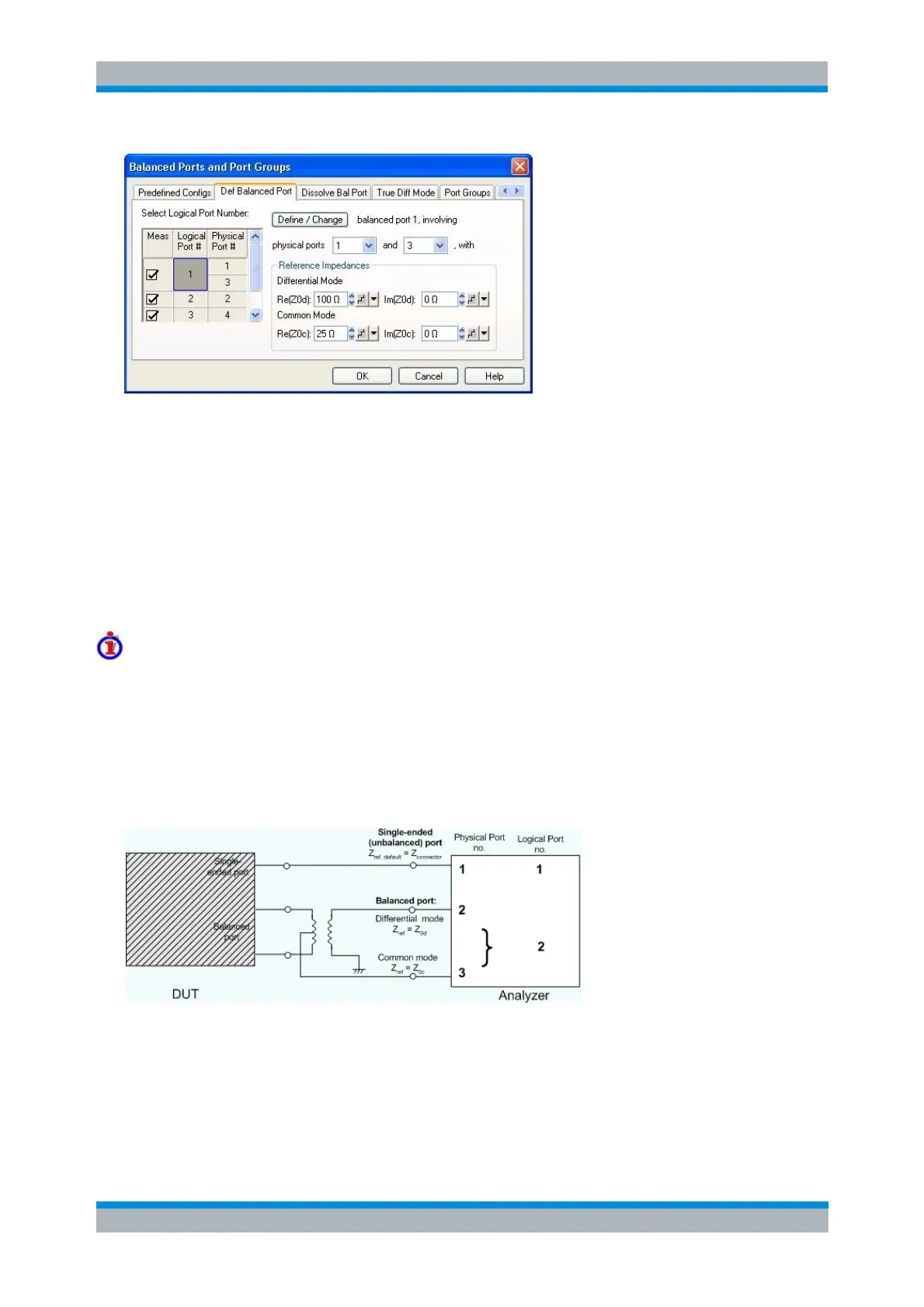
Select Logical Port Number shows the current port configuration. The selected logical port
appears on a dark background. Click on the table cell of a logical port to view and change the
settings.
A balanced port definition involves two different physical ports and the reference impedances for
differential mode and common mode waves.
Define/Change updates the balanced port configuration (including the Select Logical Port Number
table), based on the current settings. This button is required for any change of the balanced port
configuration; OK activates the settings in the Select Logical Port Number table.
Reference impedance settings
For non waveguide ports the default reference impedance is equal to the reference impedance of the
connector type assigned to the port but can be defined as an arbitrary complex value (renormalization of
port impedances). By changing the reference impedance, it is possible to convert the measured values at
50 Ω (75 Ω) into values at arbitrary port impedances. For details refer to section Virtual Transform –
Reference Impedances.
For balanced non waveguide ports it is possible to define separate complex reference impedances for
differential and for common mode.
The default values for the balanced port reference impedances are derived from the (real) default
reference impedance of the physical analyzer ports (Z
0
= 50 Ω):
The default value for the differential mode is Z
0d
= 100 Ω = 2*Z
0
.
The default value for the common mode is Z
0c
= 25 Ω = Z
0
/2.