R&S
®
ZVA / R&S
®
ZVB / R&S
®
ZVT GUI Reference
Channel Menu
Operating Manual 1145.1084.12 – 30 311
RF mixers convert an RF signal at one frequency into a signal at another frequency. The frequency to be
shifted is applied at the RF input and the frequency shifting signal (from a local oscillator, LO) is applied to
the RF mixer's LO port, resulting in an output signal at the mixer's Intermediate Frequency (IF) port.
For a given RF signal, an ideal mixer would produce only two IF outputs: one at the frequency sum of the
RF and LO (IF = RF + LO), and another at the frequency difference between the RF and LO (IF = |RF –
LO|). An additional filter can then select one of these IF outputs and reject the unwanted one.
The frequency-converting property of the mixer (i.e. the fact that incident and transmitted waves are at
different frequencies) causes a loss of phase information. While a scalar measurement is active, the
reverse transmission parameter S
12
is unavailable; the magnitude of the forward transmission parameter
S
21
describes the conversion gain. The conversion gain measurement can be improved by a source match
and load match correction. The phase information, including the group delay, is meaningless. The phase
or group delay of mixers can be analyzed in a vector mixer measurement.
In mixer mode the analyzer provides the following functionality:
Configuration of the RF and LO signals and measurement of the generated IF signal, see Define
Mixer Mode and Mixer Signal Diagrams.
Power calibration of the signal sources and of the IF receiver; see Mixer Power Calibration.
A system error correction including a possible enhanced wave correction at the RF and IF ports
(source match correction) and a load match correction; see Mixer Cal.
The mixer mode can be used to test important performance parameters of RF mixers such as
frequency ranges, conversion loss, compression, and isolation.
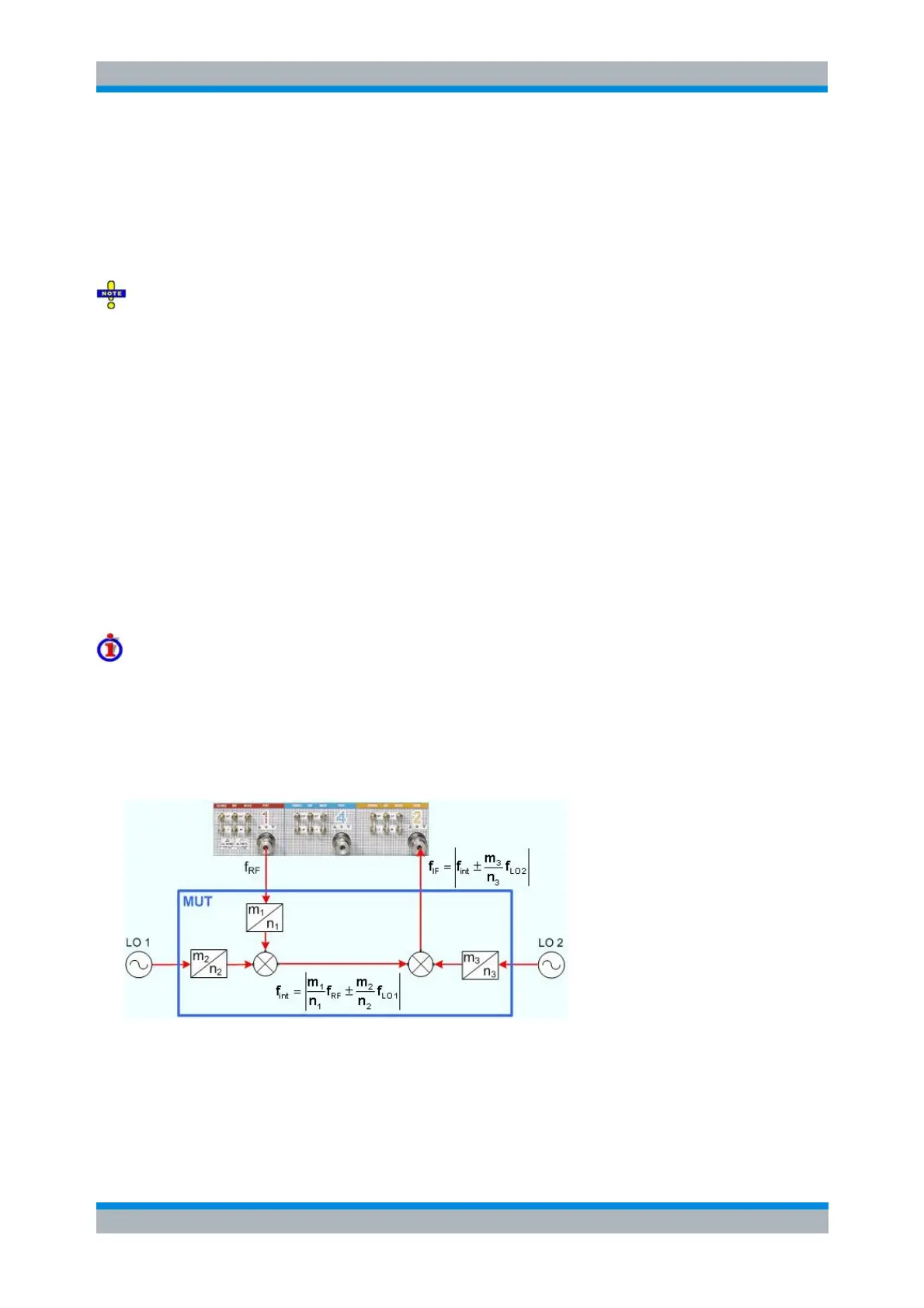
Test Setup with Two Mixers
The scalar mixer measurement is also suited for measuring a system of two mixers with frequency
multipliers at their RF and LO inputs. The RF and LO input frequencies of the first mixer are both
multiplied by an integer fraction; the converted output signal f
int
is fed to the second mixer, together with
the multiplied second LO signal. The analyzer measures the output signal of the second mixer at its IF
input port. The general test setup is shown below; the mixer system under test (MUT) is enclosed in a blue
rectangle.
The figure above also shows the possible output frequencies of the two mixers. The actual values of f
int
and f
IF
depend on the RF and LO frequencies and of the measured conversion (lower sideband or upper
sideband with up- or down-conversion). The analyzer automatically calculates all frequencies and sets its
receiver according to the settings made; see Set Frequencies.
A test setup with two mixers requires 3 independent source ports plus one receive port. An R&S ZVA67 or
one of the R&S ZVA24/40 network analyzers with four ports and four generators (order nos.