R&S
®
ZVA / R&S
®
ZVB / R&S
®
ZVT GUI Reference
Channel Menu
Operating Manual 1145.1084.12 – 30 314
Define Correction selects the system error correction type for the scalar mixer measurement.
Select the appropriate correction type according to your accuracy and speed requirements; see
table below. Notice that none of the correction types provides the phase information for
transmission S-parameters.
1. The Define Correction settings are only valid for scalar mixer measurements. The panel is
unavailable if the Define Mixer Measurement dialog is opened from another measurement (e.g. a mixer
delay or intermodulation distortion measurement).
2. The options Source Match and Source and Load Match can not be used for DUTs with embedded LO.
Required
calibration
steps
Power correction of the RF and LO sources and of the IF receiver, no phase correction,
provides scalar results (wave quantities, ratios).
Power correction plus enhanced wave correction at the RF and IF ports; see Enhanced Wave
Correction (Scalar Mixer Meas.). Channel – Calibration – Enhanced Wave Correction is
activated implicitly.
Mixer Power Cal,
Mixer Cal
Power correction plus enhanced wave correction plus Load Match Correction of the
conversion gain S
21
. Channel – Calibration – Enhanced Wave Correction and Channel –
Calibration – Load Match Correction is activated implicitly.
Mixer Power Cal,
Mixer Cal
Scalar Mixer Meas, Reset Frequency Conversion
The softkey Scalar Mixer Meas activates the scalar mixer mode, where the analyzer ports are at different
frequencies. Reset Frequency Conversion disables all frequency conversion measurements, including e.g.
an active harmonic distortion measurement.
A Mix label in the channel list indicates that a frequency conversion mode is active.
[SENSe<Ch>:]FREQuency:CONVersion MIXer | FUNDamental
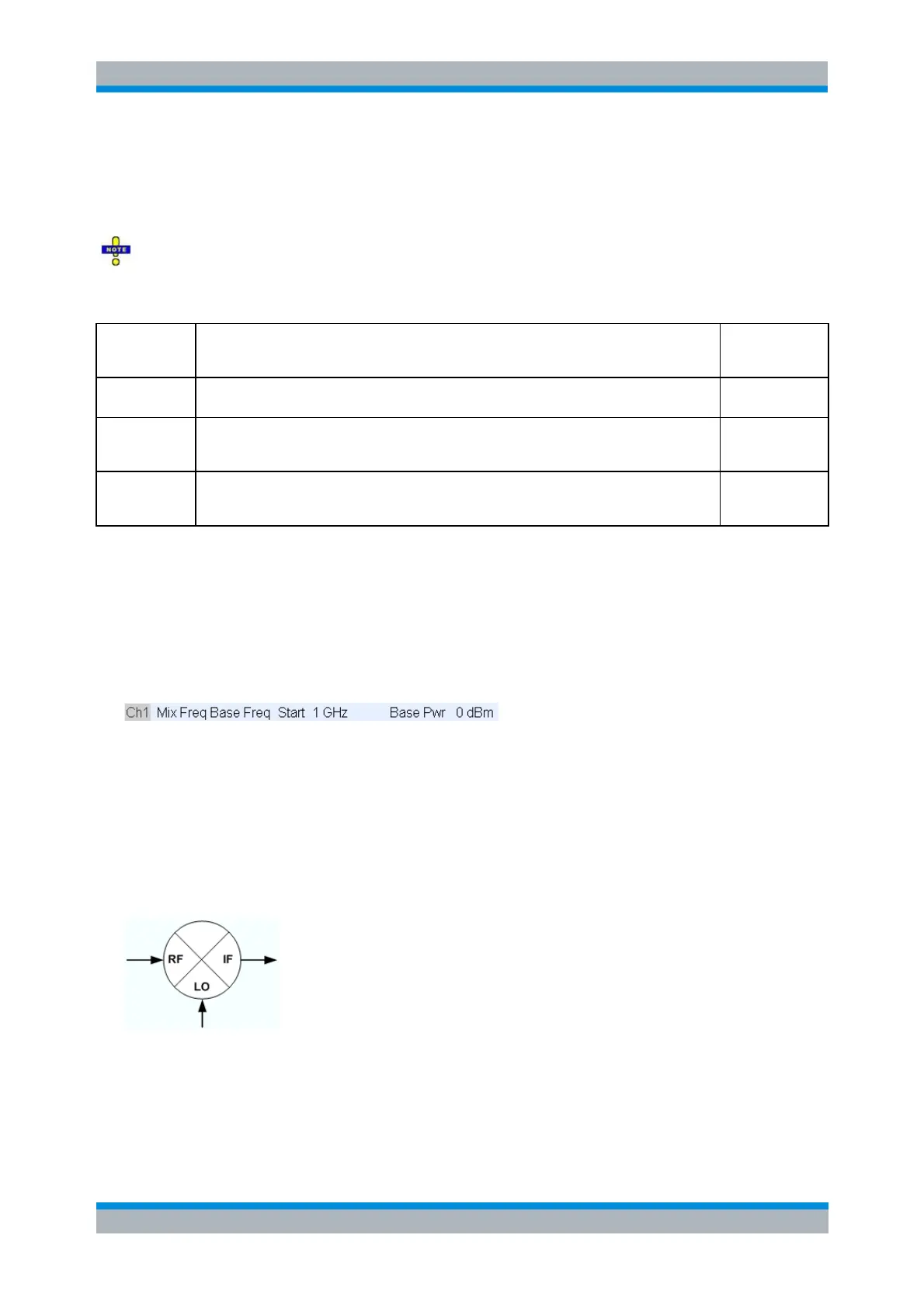
Mixer Signal Diagrams
The mixer signal diagrams show the parameters of the mixer input signals (RF, LO) and of the mixing
product (IF signal, output). The diagrams appear in the Mixer Measurement, Define Power, and Define
Frequencies dialogs.
The RF signal is the stimulus signal that the analyzer generates with the current channel settings.
After a reset the frequency and power of the RF signal is as defined in the Channel – Stimulus
menu. The RF signal parameters can be changed in the Define Power... and Define
Frequencies... dialogs.
The Local Oscillator (LO) signal is an additional RF signal that is either generated by the network