R&S
®
ZVA / R&S
®
ZVB / R&S
®
ZVT GUI Reference
Channel Menu
Operating Manual 1145.1084.12 – 30 317
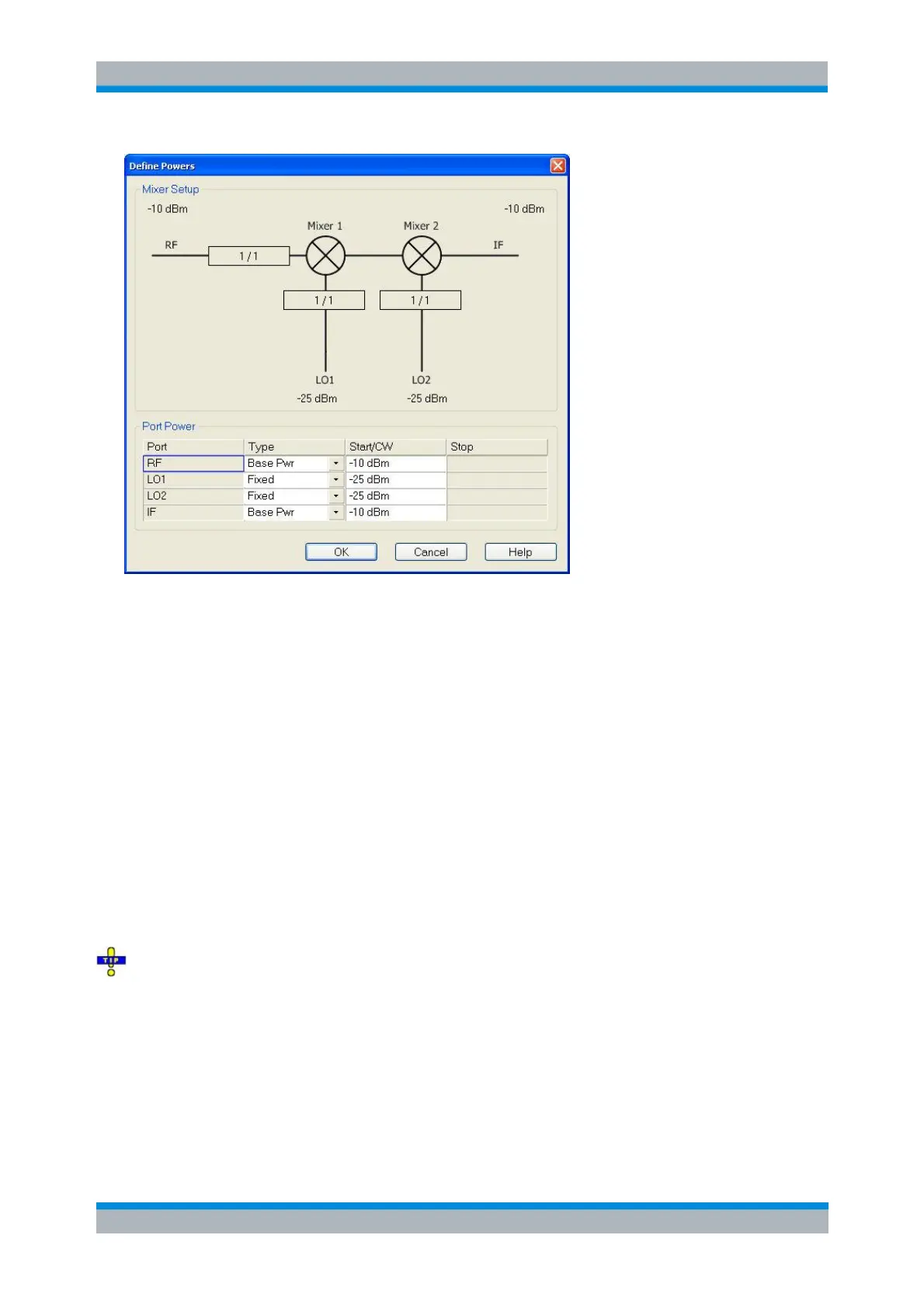
The diagram contains the mixer signal diagram with the current power levels or power ranges and a Port
Power table with the following columns:
Port contains the RF and IF ports and one or two LO ports, depending on the number of
Converter Stages selected in the mixer measurement dialog.
Type specifies how the power for each signal is defined. Each of the mixer input signals RF, LO 1,
and LO 2 (if present) can be either at the analyzer's channel base power (Base Pwr; the signal is
swept if a power sweep is active; it is at fixed power (CW) for the other sweep types) or at the
Fixed power. The same applies to the IF signal.
For vector mixer measurements, the power of the Aux LO signal (fed to the MEAS and REF
mixers) can be defined independently.
Start/CW defines the output power levels at the RF, LO 1 and LO 2 ports. The Base Pwr setting
overwrites the power settings in the Channel – Stimulus menu (for power sweeps, where Base
Pwr is the power sweep range) or Channel – Power Bandwidth Average menu (for the other
sweep types). The Fixed power settings appear in the Port Configuration dialog.
The Start/CW power for the IF port sets the IF source power for the reverse sweep. This setting is
relevant only if a Load Match Correction is active.
Stop shows the stop value of the power sweep range (for power sweeps only).
If a segmented frequency sweep with segment-specific power levels is active, the Base Pwr is no
longer editable but set to the minimum and maximum power of the sweep segments.
SOURce<Ch>:FREQuency CONVersion:MIXer:PMODe
SOURce<Ch>:FREQuency CONVersion:MIXer:PMFixed
Define Frequencies
The Define Frequencies dialog controls the frequency of the RF and the LO signal(s) and the analyzer (IF