R&S
®
ZVA / R&S
®
ZVB / R&S
®
ZVT GUI Reference
Channel Menu
Operating Manual 1145.1084.12 – 30 316
IF signal (right side): Analyzer port number (e.g. Port 2), fixed frequency = (RF + LO) or
|RF – LO|, expected power range.
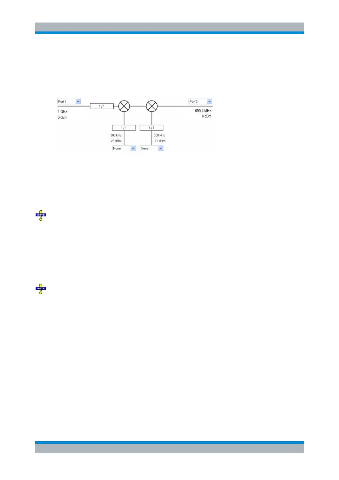
Time or CW mode sweep
The following mixer signal diagram corresponds to a Time or CW Mode sweep.
RF signal (left side): Analyzer port number (e.g. Port 1), fixed power, CW frequency,
frequency conversion settings (1 / 1 denotes no conversion).
LO signals (1 or 2, from below): Signal source (analyzer port or external generator), fixed
power, CW frequency, frequency conversion settings.
IF signal (right side): Analyzer port number (e.g. Port 2), fixed frequency = (RF + LO) or
|RF – LO|, expected fixed power.
The ports in the mixer signal diagrams are physical ports. To measure mixers with differential inputs,
define a logical port configuration and enter one of the physical ports that belong to the logical port. The
analyzer will implicitly account for the logical port settings. Balanced port configurations can also be used
in true differential mode.
Vector mixer measurements require single-ended ports.
Define Powers
The Define Powers dialog defines the power of the RF and the LO signals.
Restrictions
For vector mixer measurements (option R&S ZVA-K5), mixer delay measurements without LO access
(option R&S ZVA-K9), and long distance mixer delay measurements (option R&S ZVA-K10), only one LO
signal (corresponding to one mixer stage) is supported.