R&S
®
ZVA / R&S
®
ZVB / R&S
®
ZVT GUI Reference
Channel Menu
Operating Manual 1145.1084.12 – 30 366
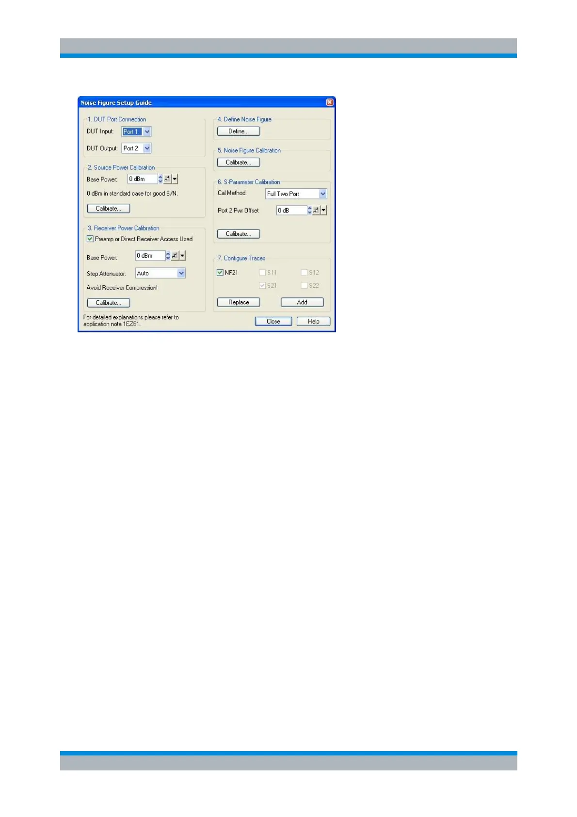
The setup guide provides the following panels/steps:
1. DUT Port Connection defines the basic test setup, i.e. the input and output ports of the DUT/NWA. With
option R&S ZVA<frequency>-B16, Direct Generator and Receiver Access, it is possible to measure the
noise figure at a single port (<DUT Input> = <DUT Output>); see section Basic Test Setup and Noise
Figure Calculation.
2. Source Power Calibration gives access to the Source Power Cal dialog for the previously selected DUT
Input port and base power. The base power setting overwrites the Channel – Power Bandwidth Average –
Power setting as soon as the calibration dialog is opened.
The ideal IF bandwidth setting for the source power calibration is smaller than the bandwidth used for the
noise figure measurement. Moreover it is advantageous to set the source attenuation to 0 dB. If the
current settings differ from the ideal values, a message box is opened where you can choose to work with
ideal calibration settings. The current settings will be restored after the calibration.
3. Receiver Power Calibration gives access to the Receiver Power Cal dialog for the previously selected
DUT Output port. If a preamplifier is connected between the DUT and the receive port of the analyzer, or if
the output signal of the DUT is fed to the MEAS IN connector of option R&S ZVA<frequency>-B16, Direct
Generator and Receiver Access, in order to bypass the coupler and improve the receiver noise figure, the
check box should be selected. This activates the input fields for the base power and source step
attenuator settings (if available), which you may have to adjust to the test setup in the receiver path in
order to avoid excess receiver input power levels (receiver compression; see data sheet). It also activates
the Port <n> Pwr Offset field in the S-Parameter Calibration panel. An active check box has no additional
effects.
The base power setting overwrites the Channel – Power Bandwidth Average – Power setting after you
confirm the Reduce IF bandwidth... message box in order to open the calibration dialog. The step
attenuator setting immediately overwrites the source attenuator settings for the DUT Input port in the
Channel – Power Bandwidth Average – Step Attenuators dialog.
4. Define Noise Figure opens the Define Noise Figure Measurement dialog, providing basic settings for
the noise figure measurement.