R&S
®
ZVA / R&S
®
ZVB / R&S
®
ZVT GUI Reference
Channel Menu
Operating Manual 1145.1084.12 – 30 368
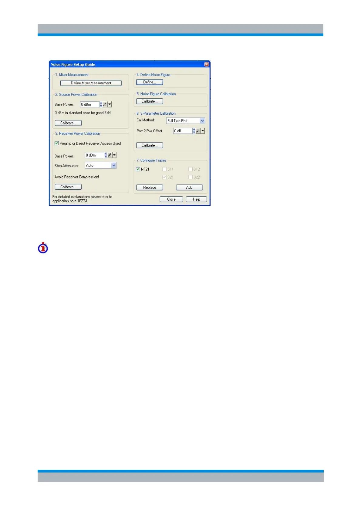
The setup guide provides the following panels/steps:
1. Define Mixer Measurement opens the Define Scalar Mixer Measurement dialog. This dialog activates
the frequency conversion mode, selects the test ports, and configures the mixer input signals.
Mixer Noise Figure Measurement with Embedded LO
Compared to a synchronized LO source with known frequency, for embedded (non-synchronized) LO
sources a different Mixer Noise Figure Measurement method is implemented.
This method uses RMS instead of AVG detectors and is selected automatically, if an Embedded LO port is
configured in the Define Scalar Mixer Measurement dialog. It produces correct results if the embedded
LO's deviation from the nominal LO frequency is "small" compared to the measurement bandwidth (e.g. <
10 kHz for the default Noise Figure Measurement setup). However, it has the following restrictions:
1. Scalar only corrections: Source Match and Source and Load Match corrections are not available
(Define Correction setting in Define Scalar Mixer Measurement)
2. Gain and noise cannot be measured in parallel (Measurement of Gain and Noise is fixed to
Sequential in Define Noise Figure Measurement dialog)
3. S-parameter results are not available (Configure Traces step of Mixer Noise Figure Setup Guide)
2. Source Power Calibration gives access to the Scalar Mixer Measurement Power Calibration dialog for
the previously selected DUT input port and Base Power. The base power setting overwrites the Channel –
Power Bandwidth Average – Power setting as soon as the calibration dialog is opened.
The ideal IF bandwidth setting for the source power calibration is smaller than the bandwidth used for the
noise figure measurement. Moreover it is advantageous to set the source attenuation to 0 dB. If the
current settings differ from the ideal values, a message box is opened where you can choose to work with
ideal calibration settings. The current settings will be restored after the calibration.
The RF source power must be calibrated in the RF and in the IF frequency range. The IF source
calibration serves as a preparative for the subsequent IF receiver calibration. For a mixer measurement
with RF image correction (enable Prepare Measurement of RF Image in the Define Scalar Mixer
Measurement dialog), an additional calibration sweep in the RF image frequency range is required.
Moreover, if a mixer measurement with Source Match or with Source and Load Match correction is active,
a source power of the IF port (in the IF frequency range) is offered.