R&S
®
ZVA / R&S
®
ZVB / R&S
®
ZVT GUI Reference
Channel Menu
Operating Manual 1145.1084.12 – 30 419
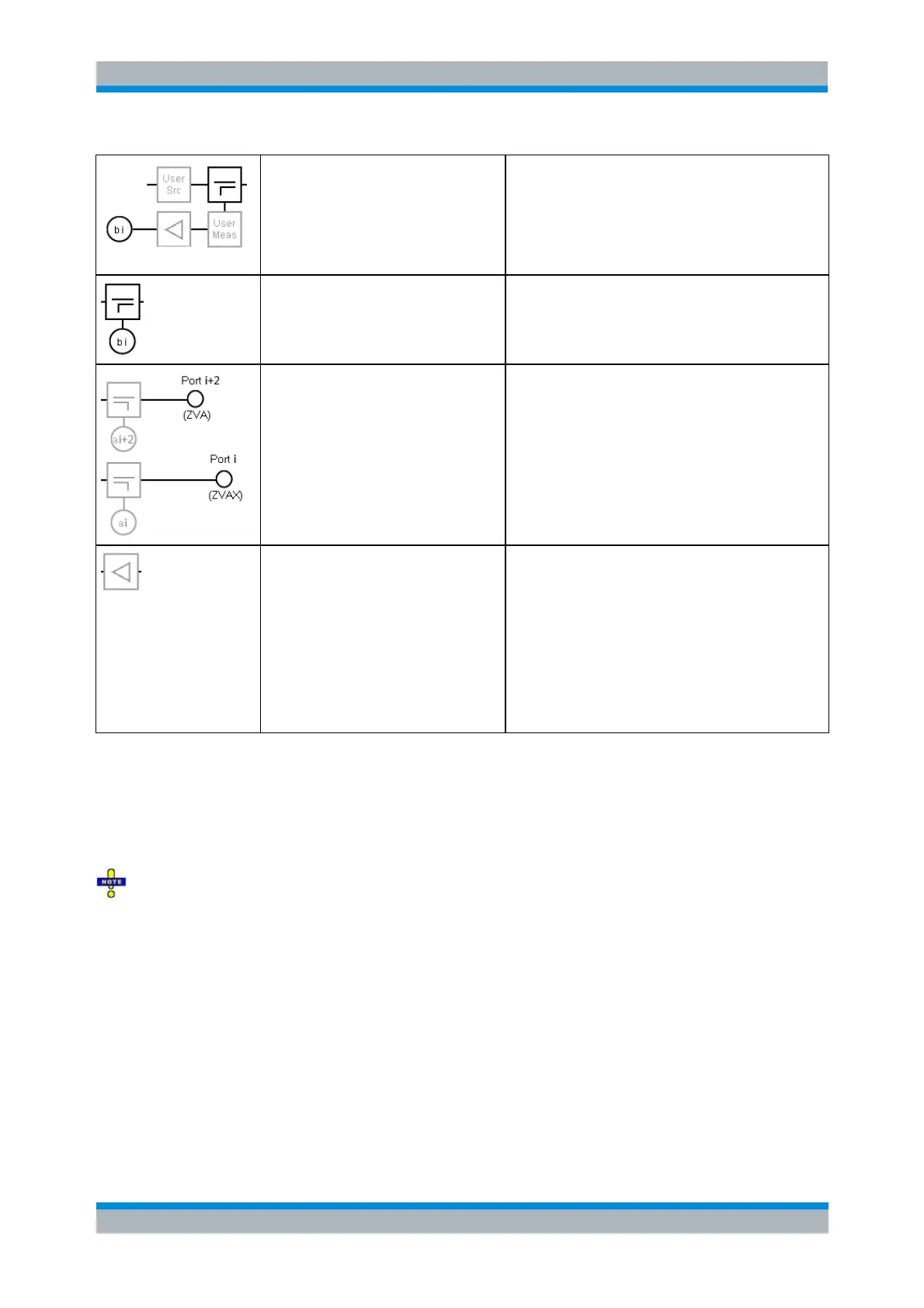
User access to source and
measurement path on the
extension unit (RF path i=1,2)
and b-wave (MEAS signal)
access
Direct access to the source and
measurement paths via SOURCE IN/OUT
and MEAS IN/OUT connectors in the lower
part or the front panel.
The b-waves are accessed at the high-power
couplers of the extension unit.
b-wave access for RF path i=3,4
The b-waves for RF paths 3 and 4 are
accessed at the couplers of the analyzer; the
MEAS path does not traverse the extension
unit.
Physical RF ports with a-wave
access at the corresponding
directional coupler
Ports 1 and 2 are located on the extension
unit and equipped with high-power couplers.
Ports 3 and 4 are located on the analyzer.
Low-noise amplifier (RF path 1,2)
If LNA i=1,2 is switched into the signal path,
the input level at port i should not exceed -30
dB (-40 dBm at User Meas); otherwise the
LNA will run into compression. This is also
indicated as a tooltip in the ZVAX-TRM
Configuration dialog.
The damage input level is +5 dBm at the
port. For details see the R&S ZVAX-TRM
data sheet.
For each path, only one a-wave access can be active at a time. b-wave access is fixed for all paths
(cannot be switched). If an optional module (pulse modulator, power amplifier, combiner, low-noise
preamplifier) is not available, its building block is replaced by a straight horizontal line (through path).
Setting up the RF path Configuration means defining which modules are looped into the signal paths and
which ones are bypassed. You can select a predefined configuration, suitable for a particular
measurement task, or choose the manual (=free) configuration mode.
The settings in the Path tab only set up the RF paths of the R&S ZVAX-TRM. Even if the selected
Configuration is targeting a particular measurement, the measurement itself must be configured as usual.
There is no automatic configuration of the related measurement.
Depending on the selected Configuration, some of the configuration options Pulsed, Power Amp and
Prepare for ALC may be selected in addition.
Default: all components are set to their PRESET configuration (by default all optional modules
and user paths are bypassed).
Config. options: -
Intermodulation P1+P3 (P2+P4): configuration suitable for intermodulation measurement
with the DUT connected to ports 1 and 2 on the extension unit and the two-tone signal at port 1
(port 2) combined from R&S ZVA ports 1 and 3 (2 and 4).
This configuration can also be used for Mixer Delay Measurements.
Config. options: Pulsed, Power Amp, Prepare for ALC.