R&S
®
ZVA / R&S
®
ZVB / R&S
®
ZVT GUI Reference
Channel Menu
Operating Manual 1145.1084.12 – 30 448
Calibration procedure
The source power calibration requires an external power meter, to be connected via GPIB bus, USB or
LAN interface. Use the USB-to-IEC/IEEE Adapter (option R&S ZVAB-B44) to control devices equipped
with a GPIB interface. The power sensor can be connected directly at the reference plane or to any other
point in the test setup where the signal power is known to be proportional to the power at the reference
plane.
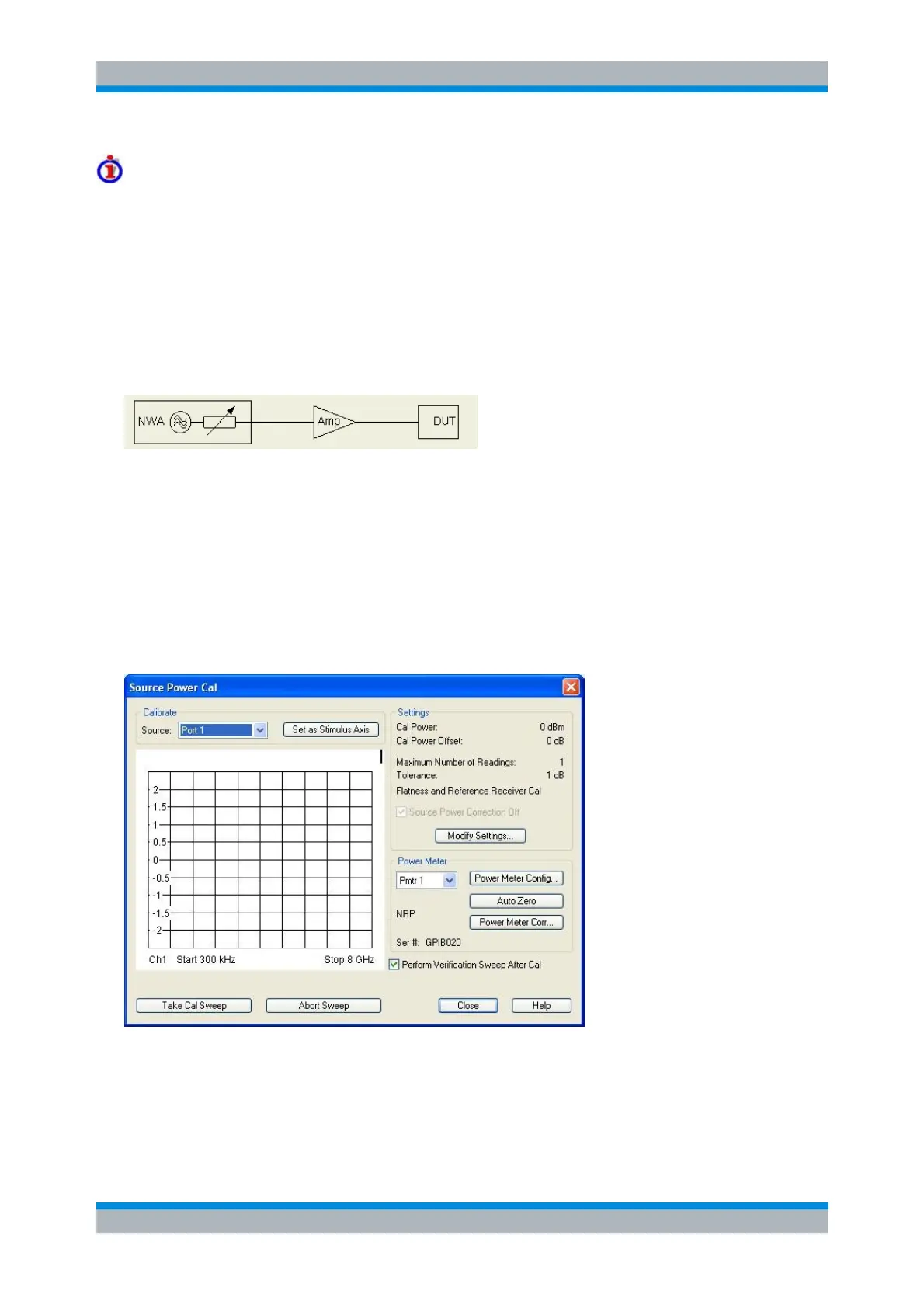
The source power calibration involves several steps:
1. The analyzer performs a first calibration sweep at the source power that is likely to produce the
target power (Cal Power) at the reference plane. A known attenuation or gain at the source port
and in the signal path between the source port and the reference plane is taken into account.
2. The power measured at the reference plane is displayed in the calibration sweep diagram and
compared to the Cal Power. The comparison serves as an input for the correction of the source power.
3. Steps 1 and 2 are repeated for a specified Number of Readings or after the deviation between the
measured power at the reference plane and the Cal Power is below a specified Tolerance.
4. After the last calibration sweep, it is possible to perform an additional Verification Sweep in order
to check the accuracy.
After a power calibration one can expect the power at the reference plane to be within the range of
uncertainty of the power meter. After a change of the sweep points or sweep range, the analyzer
interpolates or extrapolates the calibration data.
The Source Power Cal dialog provides the following control elements:
Calibrate – Source contains all analyzer ports or external generators and frequency converters
which can be used as a source for the calibrated wave quantity.
The Source list always contains the analyzer ports Port 1 to Port n.