R&S
®
ZVA / R&S
®
ZVB / R&S
®
ZVT System Overview
Screen Elements
Operating Manual 1145.1084.12 – 30 40
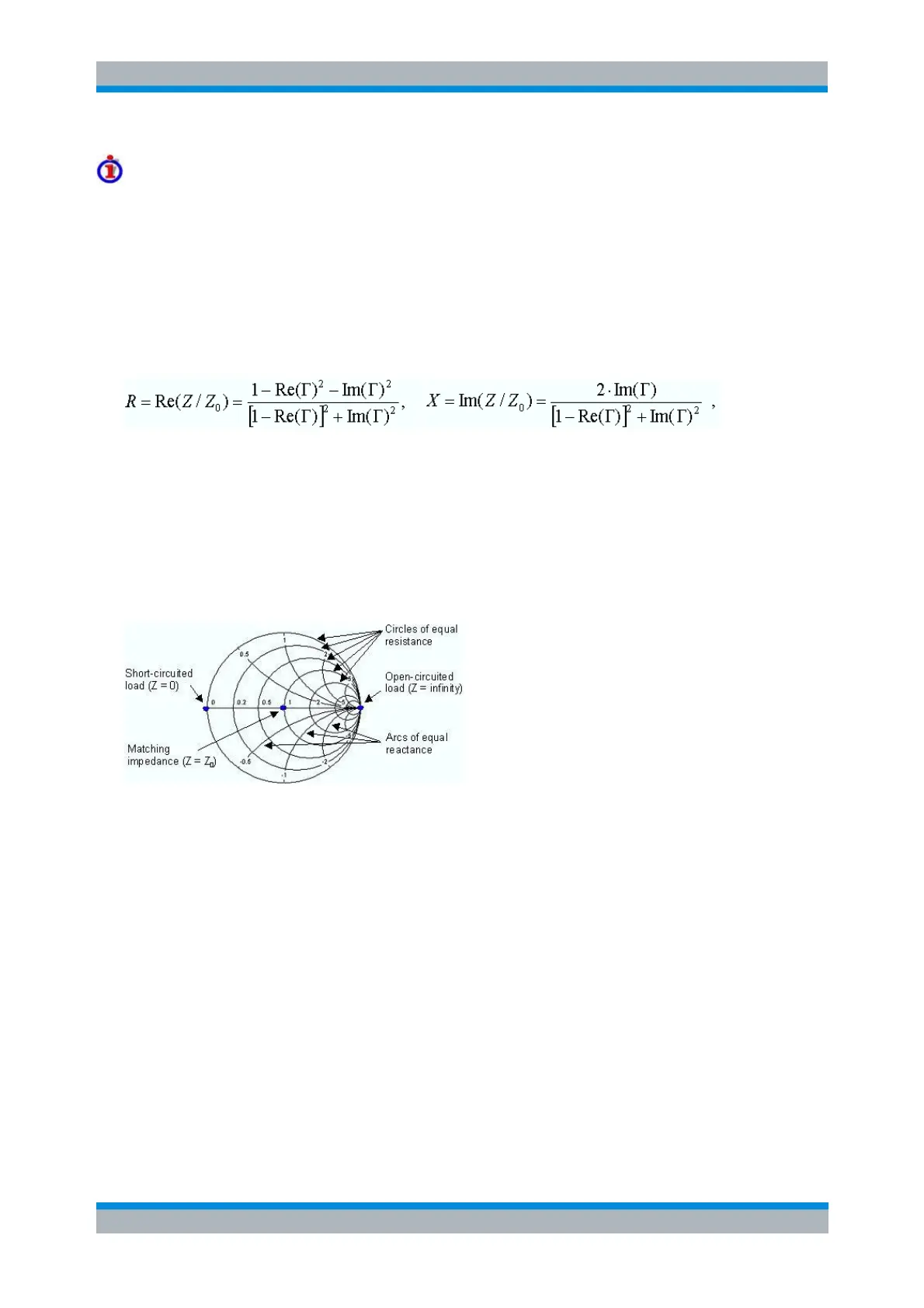
Example: Reflection coefficients in the Smith chart
If the measured quantity is a complex reflection coefficient Γ (e.g. S
11
, S
22
), then the unit Smith chart can
be used to read the normalized impedance of the DUT. The coordinates in the normalized impedance
plane and in the reflection coefficient plane are related as follows (see also: definition of matched-circuit
(converted) impedances):
Z / Z
0
= (1 + Γ) / (1 – Γ)
From this equation it is easy to relate the real and imaginary components of the complex resistance to the
real and imaginary parts of
in order to deduce the following properties of the graphical representation in a Smith chart:
Real reflection coefficients are mapped to real impedances (resistances).
The center of the Γ plane (Γ = 0) is mapped to the reference impedance Z
0
, whereas the circle
with |Γ| = 1 is mapped to the imaginary axis of the Z plane.
The circles for the points of equal resistance are centered on the real axis and intersect at Z =
infinity. The arcs for the points of equal reactance also belong to circles intersecting at Z = infinity
(open circuit point (1,0)), centered on a straight vertical line.
Examples for special points in the Smith chart:
The magnitude of the reflection coefficient of an open circuit (Z = infinity, I = 0) is one, its phase is
zero.
The magnitude of the reflection coefficient of a short circuit (Z = 0, U = 0) is one, its phase is –180
deg.
Inverted Smith Chart
The inverted Smith chart is a circular diagram that maps the complex reflection coefficients S
ii
to
normalized admittance values. In contrast to the polar diagram, the scaling of the diagram is not linear.
The grid lines correspond to points of constant conductance and susceptance.
Points with the same conductance are located on circles.
Points with the same susceptance produce arcs.
The following example shows an inverted Smith chart with a marker used to display the stimulus value,
the complex admittance Y = G + j B and the equivalent inductance L (see marker format description in the