R&S
®
ZVA / R&S
®
ZVB / R&S
®
ZVT GUI Reference
System Menu
Operating Manual 1145.1084.12 – 30 539
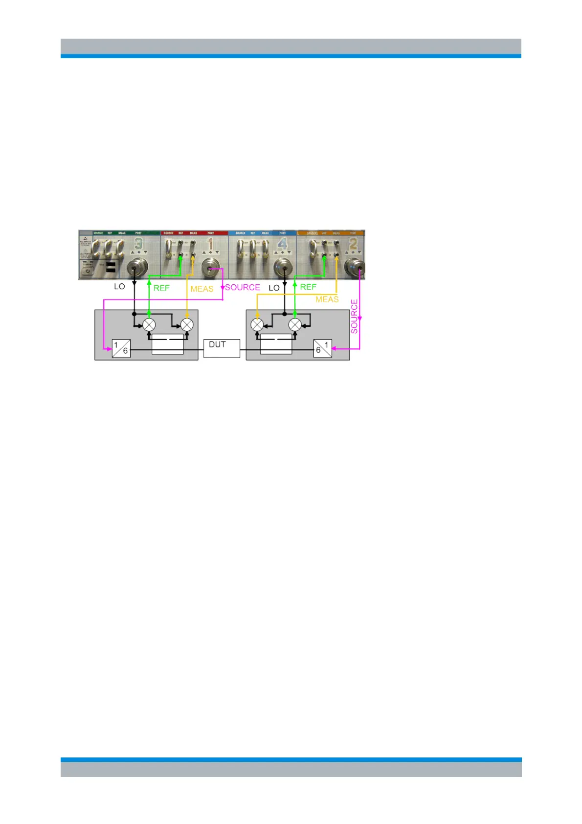
Test Setup and Principle of the Measurement
The frequency converters use frequency multipliers to transform the RF source signal from one of the
network analyzer ports into a high-frequency (mm-wave) stimulus signal. A dual directional coupler
separates the reference and measurement channels from the waveguide test port. A second signal (Local
Oscillator, LO) is used for down-conversion of the reference and measurement channels. The LO signal
can be provided either by a second analyzer port or by an external generator. The down-converted signals
are fed to the REF IN and MEAS IN input connectors of the analyzer port providing the RF source signal.
The schematic test setup for a two-port transmission measurement using four analyzer ports (no external
generator) is shown below.
The analyzer firmware supports R&S ZVA-Zxxx and R&S ZCxxx series converters. In the R&S ZVA-Zxxx
series, two models are equipped with electronic attenuators: R&S ZVA-Z90E and R&S ZVA-Z110E.
Generally, a measurement with a mm-wave converter without electronic attenuator involves the following
steps:
1. R&S ZVA-Zxxx series: Selection of the converter type and of the test setup in the Frequency
Converter dialog
R&S ZCxxx series: Connection of the converter to the NWA via USB, which enables the analyzer
firmware to automatically identify the converter type
2. Connection of the frequency converters
3. System Error Correction using a suitable waveguide calibration kit
4. Connection of the DUT and measurement
For converters with electronic attenuators, the following additional steps are required:
Entry of power coefficients that describe the transfer characteristics (att = f(I)) of the electronic
attenuator. This is only needed once (when the converter is used for the first time)
Power settings
Optionally: Power calibration for flat and accurate output power
For E-type converters or converters whose output power can be controlled by varying the input power, the
following additional steps can be performed:
Provide a 2-dimensional data array that describes the dependency of output power from input
power and frequency or, if applicable, from attenuation and frequency. The data are collected with
the R&S Converter Leveling Tool.
Power settings
If a NWA with four sources is used (R&S ZVA24 var. 28, R&S ZVA40 var. 48 or R&S ZVA67), it is
recommended to use Port 4 as a common LO drive port and split the LO by means of an external power