R&S
®
ZVA / R&S
®
ZVB / R&S
®
ZVT Measurement Examples
Calibration
Operating Manual 1145.1084.12 – 30 74
Note that the gender combinations (mm, ff or mf) of both Lines must be equal.
TRL calibration with 2 Lines
Suppose you want to perform a TRL calibration using coaxial air Lines for the sweep range between 1
GHz and 40 GHz. The through standard has length l
thr
. The ratio of the stop frequency to the start
frequency is 40, therefore an accurate calibration with a single Line standard is not possible. However, it is
possible to calibrate the entire sweep range with two Lines of different (electrical) lengths l
long
and l
short
; see
TRL Extensions.
To determine the electrical lengths of the two Lines...
1. Select the length of the longer Line such that the transmission phase of (l
long
– l
thr
) at the start
frequency of 1 GHz is equal to 20 deg: l
long
= λ (1 GHz) / 18 + l
thr
= c
0
/ (18 * 1 GHz) + l
thr
= 1.666
cm + l
thr
, where c
0
is the velocity of light. This length corresponds to a delay time of Δt
long
= 55.55
ps + l
thr
/c
0
.
2. Select the length of the shorter Line such that the transmission phase of (l
short
– l
thr
) at the stop
frequency of 40 GHz is equal to 160 deg: l
short
= 4 * λ (40 GHz) / 9+ l
thr
= 4* c
0
/ (9 * 40 GHz)+ l
thr
=
0.333 cm+ l
thr
. This length corresponds to a delay time of Δt
short
= 11.11 ps + l
thr
/c
0
.
To perform the calibration...
3. Make sure that the two Lines are included in a calibration kit, together with the Through and the
Reflect standard required for the TRL calibration. See Creating a user-defined calibration kit.
4. Still in the Calibration Kits dialog, click Export Kit... to save your settings to a cal kit file.
5. Close the Calibration Kits dialog.
6. Click Channel – Calibration – Start Cal – Two Port P1 P2 – TRL... to open the calibration wizard
(see also Manual calibration).
7. In the Physical VNA Test Port Connector(s) dialog, select your Connector type and Calibration Kit.
Click Next >.
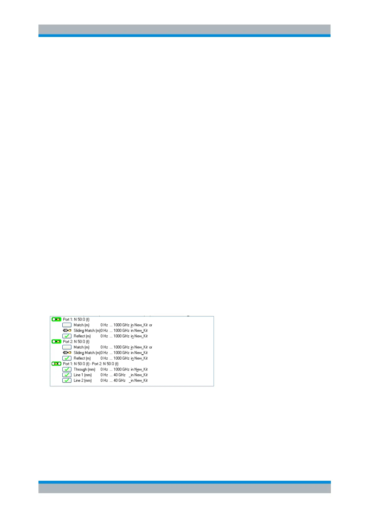
8. In the Measured Standards dialog opened, perform the calibration sweeps for all standards
including the two displayed Lines Line 1 and Line 2.
9. Click Apply to start the calculation of the system error correction data, apply them to the current
channel and close the calibration wizard.
10. Replace the last measured standard with your DUT and perform calibrated measurements without
changing the channel settings used for calibration.