10
10-195
MULTIJUNCTION TIMERS
10.8 TOU (Output-Related 24-Bit Timer)
32180 Group User’s Manual (Rev.1.0)
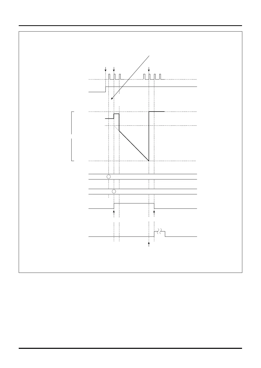
Figure 10.8.19 Typical Operation in Single-shot PWM Output Mode (Reload 0 Register: H’FFFF)
H'FFFF
H'0000
H'FFFF
H'E000
H'E000
Enabled
(by writing to the enable bit
or by external input)
Note 1: DMA transfer request also is generated with the same timing.
Note: • This diagram does not show detailed timing information.
Counter
Undefined
value
Enable bit
Reload 0 register
Reload 1 register
F/F output
Interrupt request
due to underflow
(Note 1)
Count clock
Underflow
Superficial
underflow
Data inverted by enable
Timing at which startup requests to other timers are generated
Because the reload 0 register = H'FFFF,
a superficial underflow is generated,
causing the counter to be loaded with
the content of the reload 1 register
Count down from
the reload 1
register set value
Data inverted by underflow

 Loading...


