15
15-13
EXTERNAL BUS INTERFACE
32180 Group User’s Manual (Rev.1.0)
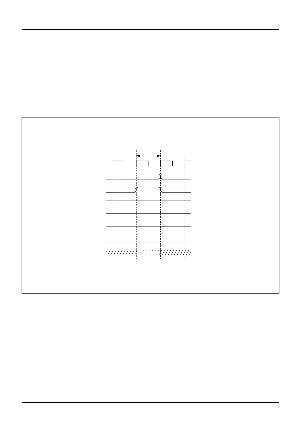
(2) When the Bus Mode Control Register = "1"
External read/write operations are performed using the address bus, data bus and the signals CS0#–CS3#,
RD#, BHE#, BLE#, WAIT# and WR#. In the external read cycle, the RD# signal is low and the BHE# or BLE#
signal output for the byte position from which to read is asserted low, with data read in from only the neces-
sary byte position of the bus. In the external write cycle, the WR# signal goes low and the BHE# or BLE#
signal output for the byte position to which to write is asserted low, with data written to the necessary byte
position.
When an external bus cycle starts, wait states are inserted as long as the WAIT# signal is low. Unless
necessary, the WAIT# signal must always be held high.
Figure 15.3.4 Internal Bus Access during Bus Free State
"H"
WR#
Bus-free state
Internal bus access
"H"
BCLK
A11–A30
CS0#–CS3#
BHE#, BLE#
DB0–DB15
WAIT#
RD#
"H"
Hi-z
(Don't Care)
Note 1: For details about the Bus Mode Control Register, see Section 15.2.3, "Bus Mode Control Register."
Notes: • Hi-Z denotes a high-impedance state.
• BCLK is not output.
Bus Mode Control Register (Note 1)
BUSMOD bit = 1 (byte enable separated)
15.3 Read/Write Operations

 Loading...


