ENGINE GENERAL INFORMATION AND DIAGNOSIS (M13 ENGINE) 6-2-45
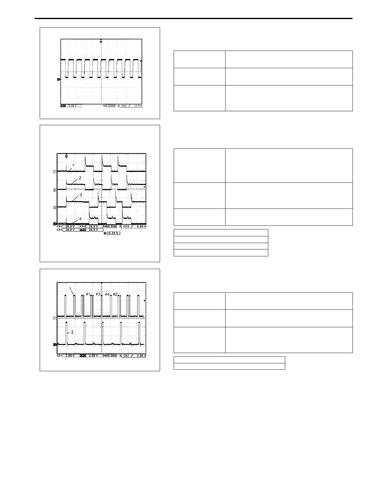
4. Reference waveform No.4
IAC valve signal
5. Reference waveform No.5
EGR valve signal
6. Reference waveform No.6
Ignition coil No.2 and No.3 signal at engine idling
Measurement
terminal
CH1: E23-8 to E23-1
Oscilloscope
setting
CH1: 5 V/DIV
TIME: 4 ms/DIV
Measurement
condition
• After warmed up to normal operating
temperature
• Engine at specified idle speed
Measurement
terminal
CH1: E23-17 to E23-1
CH2: E23-34 to E23-1
CH3: E23-16 to E23-1
CH4: E23-33 to E23-1
Oscilloscope
setting
CH1: 20 V/DIV, CH2: 20 V/DIV
CH3: 20 V/DIV, CH4: 20 V/DIV
TIME: 40 ms/DIV
Measurement
condition
At the moment of the ignition switch in
turned on
1. EGR valve stepper motor coil 1 signal
2. EGR valve stepper motor coil 2 signal
3. EGR valve stepper motor coil 3 signal
4. EGR valve stepper motor coil 4 signal
Measurement
terminal
CH1: E22-10 to E23-1
CH2: E23-31 to E23-1
Oscilloscope
setting
CH1: 2 V/DIV, CH2: 2 V/DIV
TIME: 40 ms/DIV
Measurement
condition
• After warmed up to normal operating
temperature
• Engine at specified idle speed
1. Cylinder reference signal (CMP reference signal)
2. No.2 and No.3 ignition signal