6-2-46 ENGINE GENERAL INFORMATION AND DIAGNOSIS (M13 ENGINE)
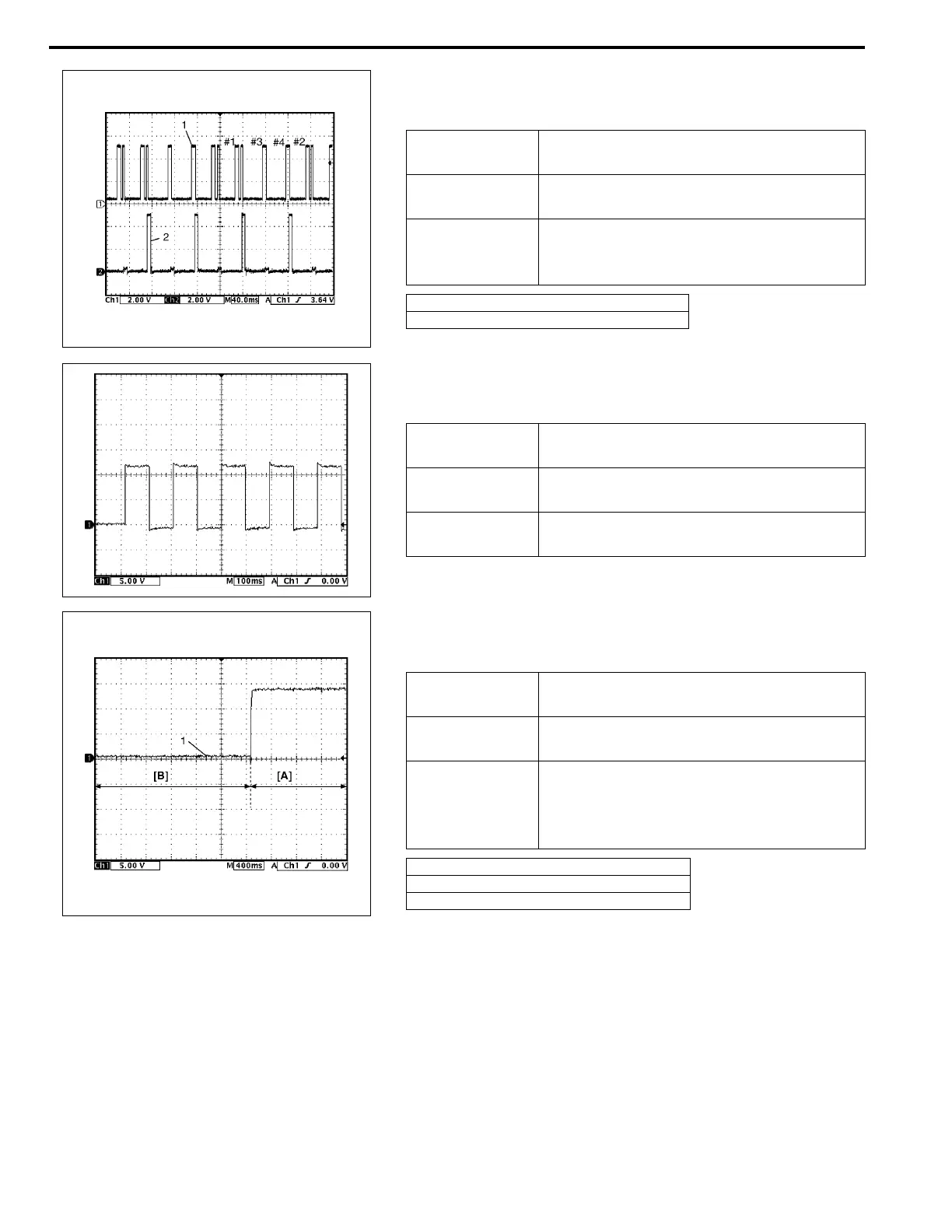
7. Reference waveform No.7
Ignition coil No.1 and No.4 signal at engine idling
8. Reference waveform No.8
Oil control valve signal at engine idling
9. Reference waveform No.9
Oil control valve signal at vehicle driving
Measurement
terminal
CH1: E22-10 to E23-1
CH2: E23-32 to E23-1
Oscilloscope
setting
CH1: 2 V/DIV, CH2: 2 V/DIV
TIME: 40 ms/DIV
Measurement
condition
• After warmed up to normal operating
temperature
• Engine at specified idle speed
1. Cylinder reference signal (CMP reference signal)
2. No.1 and No.4 ignition signal
Measurement
terminal
CH1: E22-3 to E23-1
Oscilloscope
setting
CH1: 5 V/DIV
TIME: 2 ms/DIV
Measurement
condition
At the moment of the ignition switch in
turned on
Measurement
terminal
CH1: E22-3 to E23-1
Oscilloscope
setting
CH1: 5 V/DIV
TIME: 2 ms/DIV
Measurement
condition
• After warmed up to normal operating
temperature
• Drive vehicle at 20 km/h (12 mil/h) and
depress accelerator pedal fully
[A]: Accelerator pedal depress fully
[B]: Accelerator pedal depress partially
1. Oil control valve signal