6-2-48 ENGINE GENERAL INFORMATION AND DIAGNOSIS (M13 ENGINE)
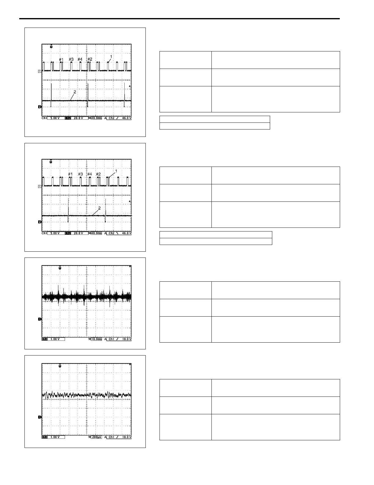
13. Reference waveform No.13
No.2 fuel injector signal at engine idling
14. Reference waveform No.14
No.1 fuel injector signal at engine idling
15. Reference waveform No.15
Knock sensor signal at engine speed 4000 r/min.
16. Reference waveform No.16
Knock sensor signal at engine speed 4000 r/min.
Measurement
terminal
CH1: E22-10 to E23-1
CH2: E22-6 to E23-1
Oscilloscope
setting
CH1: 5 V/DIV, CH2: 20 V/DIV
TIME: 40 ms/DIV
Measurement
condition
• After warmed up to normal operating
temperature
• Engine at specified idle speed
1. Cylinder reference signal (CMP reference signal)
2. No.2 fuel injector signal
Measurement
terminal
CH1: E22-10 to E23-1
CH2: E22-7 to E23-1
Oscilloscope
setting
CH1: 5 V/DIV, CH2: 20 V/DIV
TIME: 40 ms/DIV
Measurement
condition
• After warmed up to normal operating
temperature
• Engine at specified idle speed
1. Cylinder reference signal (CMP reference signal)
2. No.1 fuel injector signal
Measurement
terminal
CH1: E22-9 to E23-1
Oscilloscope
setting
CH1: 1 V/DIV
TIME: 10 ms/DIV
Measurement
condition
• After warmed up to normal operating
temperature
• Run engine at 4000 r/min.
Measurement
terminal
CH1: E22-9 to E23-1
Oscilloscope
setting
CH1: 1 V/DIV
TIME: 200
µ
s/DIV
Measurement
condition
• After warmed up to normal operating
temperature
• Run engine at 4000 r/min.