ENGINE GENERAL INFORMATION AND DIAGNOSIS (M13 ENGINE) 6-2-49
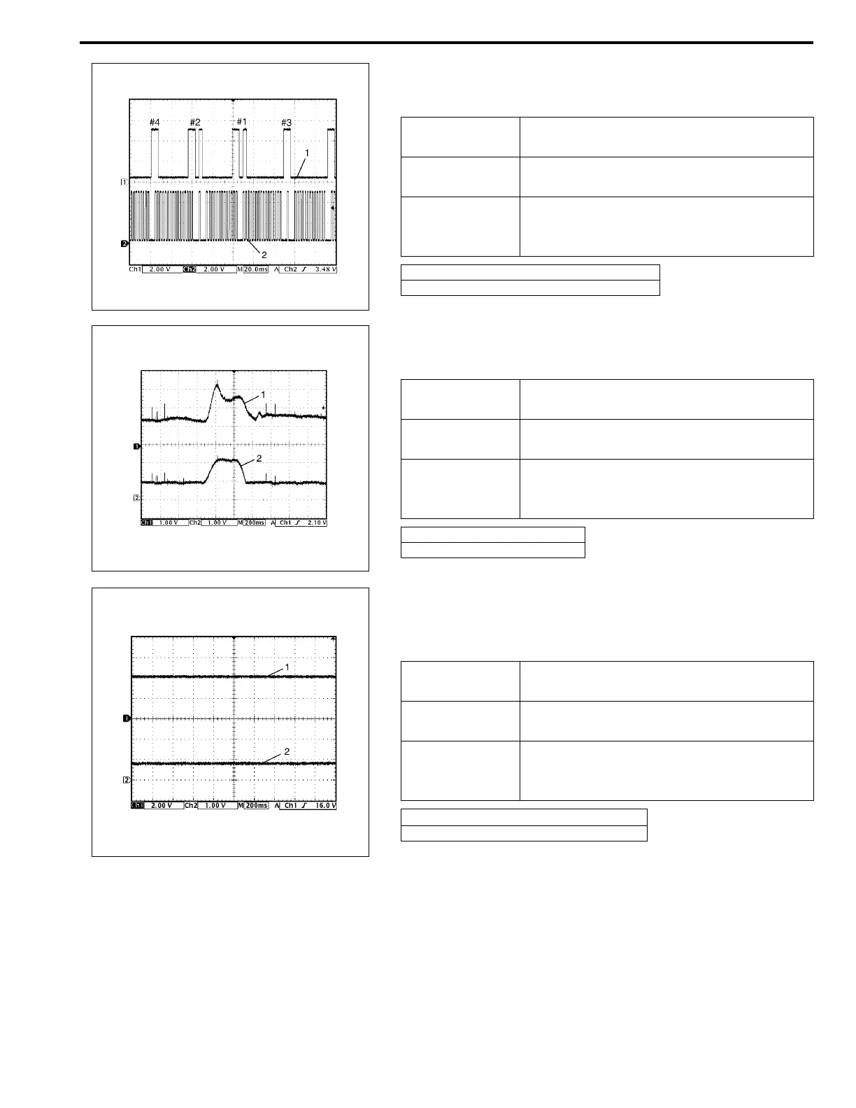
17. Reference waveform No.17
CMP sensor signal at engine idling
18. Reference waveform No.18
Mass air flow sensor signal at engine racing
19. Reference waveform No.19
Manifold absolute pressure sensor signal at ignition switch turned
ON
Measurement
terminal
CH1: E22-10 to E23-1
CH2: E22-30 to E23-1
Oscilloscope
setting
CH1: 2 V/DIV, CH2: 2 V/DIV
TIME: 20 ms/DIV
Measurement
condition
• After warmed up to normal operating
temperature
• Engine at specified idle speed
1. Cylinder reference signal (CMP reference signal)
2. CKP signal
Measurement
terminal
CH1: E22-14 to E22-28
CH2: E22-34 to E22-28
Oscilloscope
setting
CH1: 1 V/DIV, CH2: 1 V/DIV
TIME: 200 ms/DIV
Measurement
condition
• After warmed up to normal operating
temperature
• Engine racing
1. Mass air flow sensor signal
2. Throttle position sensor signal
Measurement
terminal
CH1: E22-15 to E22-28
CH2: E22-34 to E22-28
Oscilloscope
setting
CH1: 2 V/DIV, CH2: 2 V/DIV
TIME: 200 ms/DIV
Measurement
condition
• After warmed up to normal operating
temperature
• Ignition switch turned ON
1.
Manifold absolute pressure sensor
signal
2. Throttle position sensor signal