3D-14 FRONT SUSPENSION
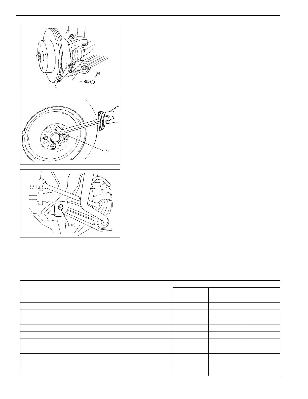
3) Install ball stud (2) to knuckle (1). Align ball stud groove with
knuckle bolt hole as shown.
Then install ball stud bolt from the direction as shown.
Tighten control arm ball stud bolt to specified torque.
Tightening torque
Control arm ball stud bolt
(a): 60 N
·
m (6.0 kg-m, 43.5 lb-ft)
4) Install wheel and tighten wheel bolts to specified torque.
Tightening torque
Wheel bolt (a): 95 N
·
m (9.5 kg-m, 69.0 lb-ft)
5) Lower hoist and vehicle in non-loaded condition, tighten con-
trol arm mounting bolt (1) to specified torque.
Tightening torque
Control arm mounting bolt (a): 60 N
·
m (6.0 kg-m, 43.5 lb-ft)
• Install stabilizer bar, referring to “Stabilizer Bar Installation” in
this section.
Tightening Torque Specifications
Fastening part
Tightening torque
N•m kg-m lb-ft
Brake caliper carrier bolt 95 9.5 69.0
Brake disk screw 9 0.9 6.5
Castle nut 50
– 150
5.0
–
15.0 36.5
–
108.5
Control arm ball stud bolt 60 6.0 43.5
Control arm mounting bolt 60 6.0 43.5
Drive shaft nut 175 17.5 127.0
Stabilizer bar bracket bolt 45 4.5 32.5
Strut bracket bolt 115 11.5 83.5
Strut support nut 23 2.3 17.0
Tie-rod end nut 40 4.0 29.0
Wheel bolt 95 9.5 69.0