09/2007
4-20
Phaser 8860/8860MFP Service Manual
REP 2.0.2
Initial Issue
Repairs and Adjustments
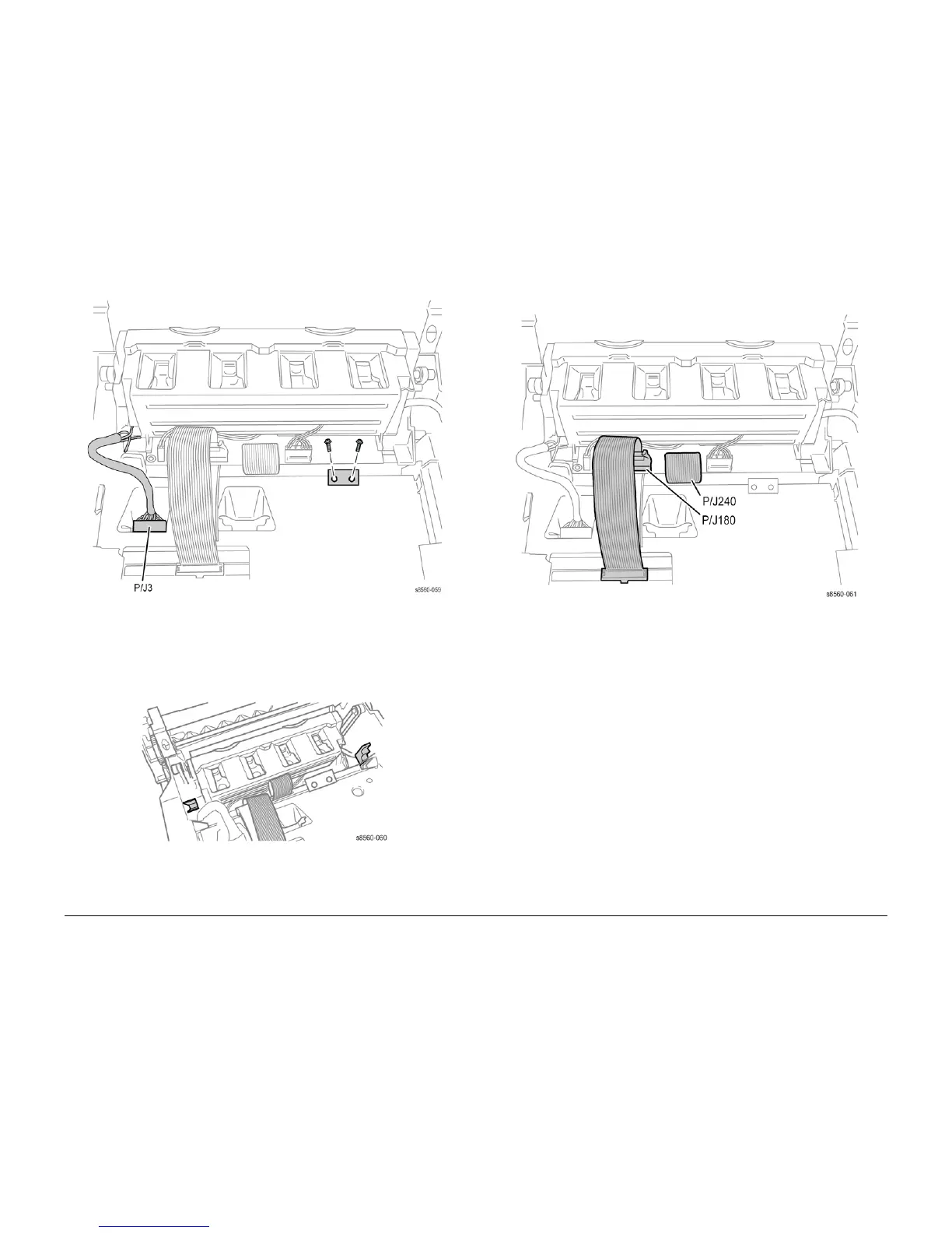
Figure 8 Printhead Electrical Connections
15. Remove the 2 (metal, T-20) screws that secure the Ground Strap.
16. Push the Air Hose into the chassis.
17. Lift the Printhead, using the finger recesses as shown in Figure 11, and place the ends of
the shaft in the cradle notches provided near the top of the frame as shown in Figure 9.
Figure 9 Printhead Cradle Notch Location
NOTE: Unlock the connectors before disconnecting the ribbon cables.
18. Disconnect the remaining 2 ribbon cables P/J180 and P/J240 from the Printhead.
Figure 10 Printhead Cable Connections
19. Remove the Printhead as shown in Figure 11, using the Finger recesses provided.
 Loading...


