09/2007
4-47
Phaser 8860/8860MFP Service Manual
REP 3.0.7
Repairs and Adjustments
Initial Issue
c. Remove the (plastic, T-20) screw connecting the Exit Module and Back Frame.
7. Remove these components from the left side:
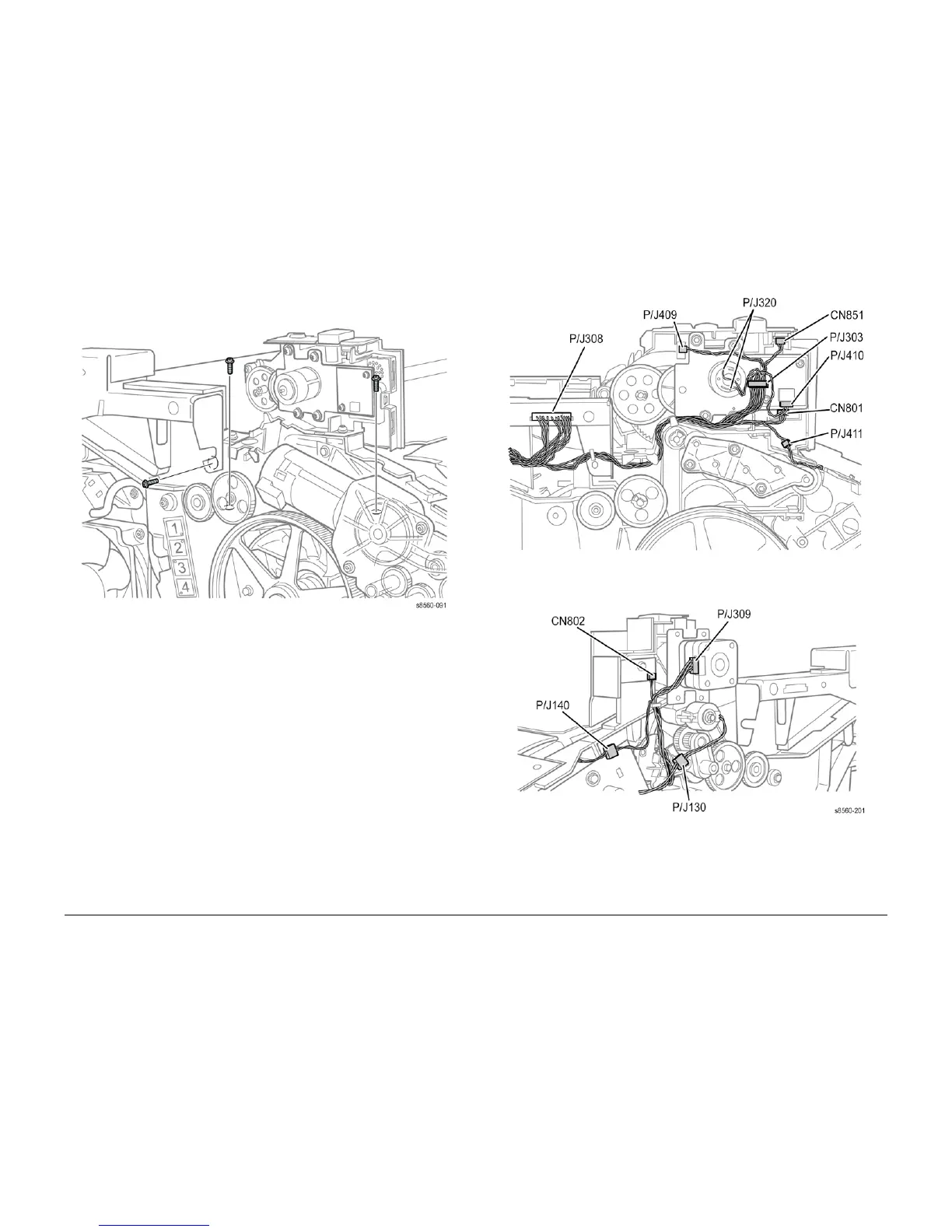
Figure 2 Exit Module Left Side Fasteners
a. Loosen the Media Drive Assembly to remove the left front screw. See REP 4.0.14.
b. Remove the left rear screw located behind the large Wiper Assembly gear.
c. Remove 1 (plastic, T-20) screw that connects the Exit Module and ground wire to the
Back Frame.
8. Disconnect these connections. See Figure 3:
• Output Tray Full Sensor (CN801 and CN802)
• Front Exit Module Harness (P/J303)
• Speaker (P/J410)
• Elevator Position Sensor (P/J409)
• Scanner Detect Sensor (CN851)
• Exit Module Harness (P/J308)
• Exit Door Interlock Switch (P/J411)
• Drum Temperature Sensor (P/J870) on the I/O Board.
• Front Door Interlock (P/J140).
• Head Maintenance Clutch (P/J130).
• I/O Board connector (P/J680).
Figure 3 8860MFP Exit Module Harness Connections
9. Lift the Exit Module from the chassis.
Replacement
Transfer the Front Exit Module Harness to the replacement part, and Perform ADJ 2.5.1 after
replacing the Exit Module.

 Loading...


