09/2007
6-6
Phaser 8860/8860MFP Service Manual
Service Diagnostics
Initial Issue
Diagnostics
Entering Service Diagnostics
Print Engine Tests: In general, diagnostic testing is assumed to be done with the system in a
“diagnostic configuration.” This means the following applies:
• Doors are closed unless instructed otherwise.
• The print engine is thermally warm (at nominal printing temperatures).
• All axis’s are or have been moved to their HOME position (run MECH INIT function).
• Trays are inserted and contain A/A4 media, unless instructed otherwise.
The tests may also be performed with the system operating at less than normal printing tem-
peratures, but may produce slightly less typical results.
NOTE: While the heaters are On, the Y-Axis is turning (to keep the Drum heating even), and
the Drum Fan may be active. The Exercise Menu -> Heaters -> All Off function disables ther-
mal regulation if access to these areas is necessary. The background thermal regulation is
reactivated by the Exercise Menu -> Heaters -> All On function if the system is still warm
enough. Turning off a single heater does NOT disable this function and the heater may be
turned back on following the next check test or reboot. The Electronics Module Fan is always
active.
Test Selection Diagnostics Mode:
The Test Selection mode provides limited access to diagnostic tests, and is typically used dur-
ing remote customer support activity where the customer is being directed to run the test and
report results by a support representative.
NOTE: Before running any diagnostic test, prepare the system according to test requirements.
To enter Test Selection mode from Customer mode and display the Test Selection screen:
1. Select Information -> Troubleshooting -> Service Tools from the Control Panel.
2. Scroll down to Enter Diagnostics and press the OK button.
When the system transitions from Customer mode into Test Selection mode, the initial Control
Panel display is the Test Selection screen as follows:
Diagnostics Menu 19.212.0
Test: 000 None Selected
The Diagnostics Menu revision number identifies the system and diagnostics firmware ver-
sions. The first two identify the system firmware version. The last digit identifies the Diagnostics
Firmware version. The Test number (000) is entered using the Up or Down buttons. The cur-
rently selected Test appears next to the number. Run the test by pressing the OK button. At
that point, the display changes to the name of the test, followed by a series of status messages
providing a general idea of the current test activity. When the test completes, the display
changes to display the results.
In some menus the subsystems are identified as follows:
• FP - Control Panel Module subsystem
• EM - Exit Module subsystem
• SM - Scanner Module subsystem
• DH - Doc Handler Module (DADF) subsystem
• FM - FAX Module subsystem
Test 000 is inoperative and causes no response if the OK button is pressed. To return to Cus-
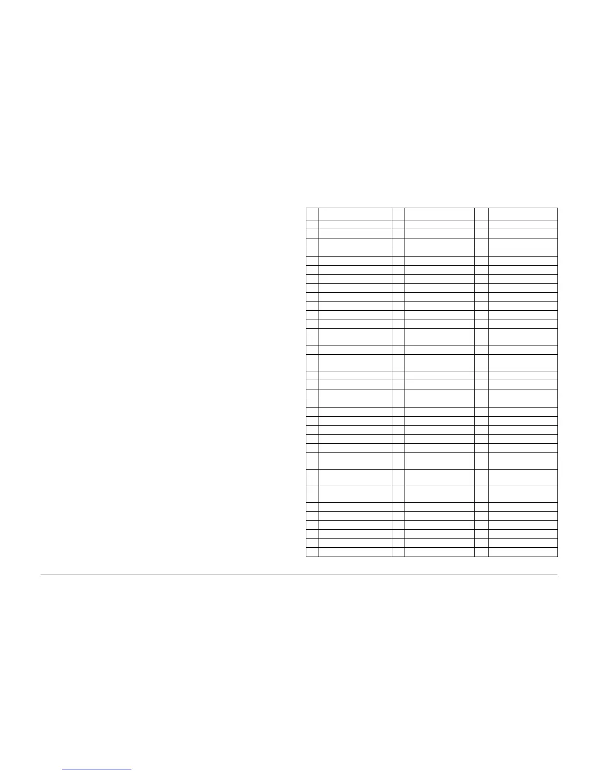
tomer mode, run test 001. Ta bl e 1lists the available tests.
Table 1 Test Selection Numbers
No. Test Name No. Test Name No. Test Name
0 No test selected 44 Transfix Drive 88 Report EM Status
1 Exit Diagnostics 45 Drum Maintenance Drive 89 Monitor EM Sensors
2 Paper Path Status 46 Tilt Drive 90 Exercise EM Home Seq
3 Temperature Status 47 Tray 2 Lift Plate Drive 91 Exercise EM Lift Seq
4 Head Maintenance Clutch 48 Tray 3 Lift Plate Drive 92 Exercise EM Roller Drive
5 Deskew Clutch 49 Tray 4 Lift Plate Drive 93 Test EM Subsystem
6 Strip Solenoid 50 Y-axis Encoder 94 Reset EM Subsystem
7 Tray 1 Pick Solenoid 51 Y-axis Geometry 95 Report SM FW Version
8 Tray 2 Pick Clutch 52 Y-axis Drive 96 Report SM Status
9 Tray 3 Pick Clutch 53 Y-axis Belt Slip 97 Report SM Lamp Status
10 Tray 4 Pick Clutch 54 Y-axis Belt Tension 98 Monitor SM Sensors
11 Tilt Solenoid 55 Stripper Contact 99 Exercise SM DRAM
12 Purge Vent Solenoid 56 Drum Maintenance Con-
tact
100 Exercise SM Axis Motion
13 Drum Heater Relay 57 Y-axis Motor 101 Exercise SM Axis Unlock
14 Deskew Shaft 58 X-axis Motor 102 Exercise SM Data Cap-
ture
15 Wiper Shaft 59 Process Motor 103 Exercise SM Lamp
16 Tray 1 Pick Shaft 60 Media Path Motor 104 Test SM Subsystem
17 Tray 2 Pick Shaft 61 Tray 2 Lift Motor 105 Reset SM Subsystem
18 Tray 3 Pick Shaft 62 Tray 3 Lift Motor 106 Report DH FW Version
19 Tray 4 Pick Shaft 63 Tray 4 Lift Motor 107 Report DH Status
20 Drum Fan 64 Tray 3 Pick/Feed Motor 108 Report DH Lamp Status
21 Electronics Fan 65 Tray 4 Pick/Feed Motor 109 Report DH Paper Status
22 Reservoir Heater 66 Purge Pump 110 Monitor DH Sensors
23 Jetstack Left Heater 67 Voltages 111 Exercise DH DRAM
24 Jetstack Right Heater 68 Line Voltage 112 Exercise DH Data Cap-
ture
25 Preheat Heater 69 Wiper Alignment 113 Exercise DH Cal Sheet
Motion
26 Drum Heater 70 Drum Maint/Transfix
Home
114 Exercise DH Feed
Motion
27 Ink Melt 1 Heater 71 Printhead Clearance 115 Exercise DH Lamp
28 Ink Melt 2 Heater 72 Transfix Gap 116 Test DH Subsystem
29 Ink Melt 3 Heater 73 Access PE NVRAM Para 117 Reset DH Subsystem
30 Ink Melt 4 Heater 74 Clear Fault History 118 Report FW Version
31 Clear Heater Data 75 Clear ISC Fault 119 Report Status
32 Paper Drive Power 76 Clear PS NVRAM 120 Report Line Status
 Loading...


