09/2007
6-30
Phaser 8860/8860MFP Service Manual
Print Engine Check Menu Tests
Initial Issue
Diagnostics
Drum Maintenance Contact Test
This test exercises the Drum Maintenance Kit. The Drum is driven by a low amplitude vibration
and the Drum Maintenance Kit is advanced through its cycle. The reaction of the Drum servo
error signal indicates when the drum was contacted by the roller and blade.
Motors Menu
This menu contains a test for each of the system motors.
Y-Axis Motor Test
The Y-Axis motor is moved to the Home position, then turned On and run slowly for one revolu-
tion. The slow motion removes the effect of inertia from the test, and the one revolution avoids
a large system status change via any permanently connected loads. With the slow operating
speed used by the test, the motor may stall at a bad commutator segment. Unusual average
values might indicate a weak motor. The motor following error, drive voltage, and power ripple
values indicate how smoothly the motor is able to turn through one revolution. Depending on
the mechanical state of the drive when this test is run, both the ripple and average values may
vary significantly from run to run due to the variation in the external load.
X-Axis Motor Test
The X-Axis motor is turned On and run slowly for one revolution. The slow motion removes the
effect of inertia from the test, and the one revolution avoids a large system status change via
any permanently connected loads. With the slow operating speed used by the test, the motor
may stall at a bad commutator segment. The connected drive cone could modify the drive
power values if the threads were defective, dry, or if the guide notch was disengaged. The A
and B voltage measurements should remain constant if the drive is operating properly.
Process Motor Test
The Process Drive motor is moved to the Home position, then the motor is jogged CW until it
begins to engage the Drum Maintenance Kit. Next, the motor is run slowly CCW for one revolu-
tion. The slow motion removes the effect of inertia from the test, and the one revolution avoids
a large system status change via any permanently connected loads. With the slow operating
speed used by the test, the motor may stall at a bad commutator segment. Unusual average
values might indicate a weak motor. The motor following error, drive voltage, and power ripple
values indicate how smoothly the motor is able to turn through one revolution.
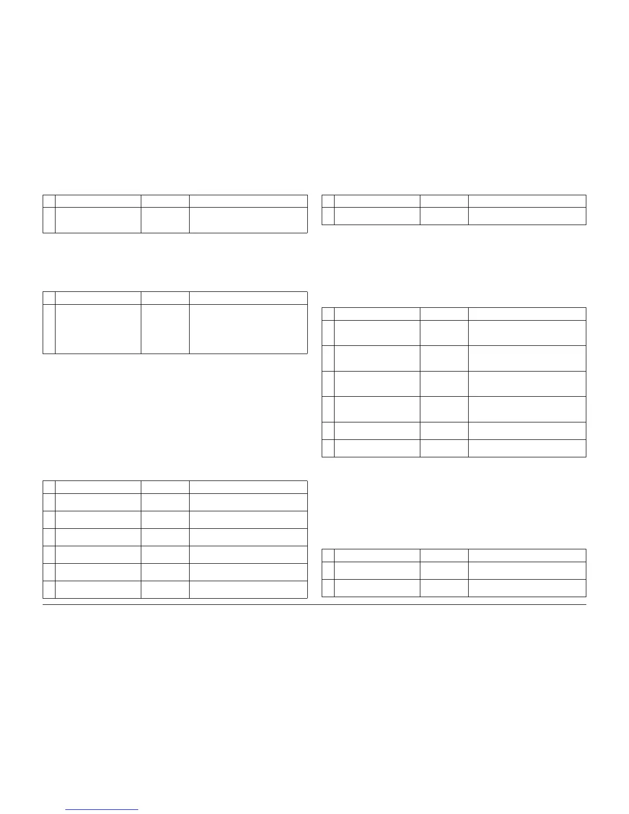
7 Releasing Amplitude (mpts) N/A Reports the magnitude of the reaction of
the Drum to the withdrawal of the blade.
See R3.
Table 39 Drum Maintenance Contact Nominal Values
R# Characteristic Typical Value Result
0 Initial Contact Position (Pro-
cess Motor counts)
N/A Reports the distance the Process Motor
was moved (raising the Drum Mainte-
nance Kit, before a Y-Axis reaction was
detected. Shows that the Drum Mainte-
nance Kit is raising and provides infor-
mation on the blade/drum gap.
Table 40 Y-Axis Motor Nominal Values
R# Characteristic Typical Value Result
0 Motor following error ripple
(ticks)
N/A Reports variation of the motor following
error over the recording interval.
1 Motor following error aver-
age (ticks)
N/A Reports the motor following error aver-
age value of the recording interval.
2 Motor drive voltage ripple
(volts)
N/A Reports amount of variation of the motor
drive voltage over the recording interval.
3 Motor drive voltage (volts) N/A Reports the motor drive voltage average
value of the recording interval.
4 Motor drive power ripple
(watts)
N/A Reports variation of the motor drive
power over the recording interval.
5 Motor drive power average
(watts)
N/A Reports the motor drive power average
value of the recording interval.
Table 38 Stripper Contact Nominal Values
R# Characteristic Typical Value Result
6 Motor performance N/A Reports the ability of the motor to
respond to servo commands.
Table 41 X-Axis Motor Nominal Values
R# Characteristic Typical Value Result
0 Motor Voltage A Ripple
(volts)
N/A Reports amount of variation of the motor
phase A drive voltage over the recording
interval.
1 Motor Voltage A Average
(volts)
N/A Reports the motor phase A drive voltage
average value over the recording inter-
val.
2 Motor Voltage B Ripple
(volts)
N/A Reports amount of variation of the motor
phase B drive voltage over the recording
interval.
3 Motor Voltage B Average
(volts)
N/A Reports the motor phase B drive voltage
average value over the recording inter-
val.
4 Motor Drive Power Ripple
(watts)
N/A Reports amount of variation of the motor
drive power over the recording interval.
5 Motor drive power average
(watts)
N/A Reports the motor drive power average
value of the recording interval.
Table 42 Process Motor Nominal Values
R# Characteristic Typical Value Result
0 Motor following error ripple
(ticks)
N/A Reports variation of the motor following
error over the recording interval.
1 Motor following error aver-
age (ticks)
N/A Reports the motor following error aver-
age value of the recording interval.
Table 40 Y-Axis Motor Nominal Values
R# Characteristic Typical Value Result
 Loading...


