09/2007
8-7
Phaser 8860/8860MFP Service Manual
System Electronics
Theory of Operation
Initial Issue
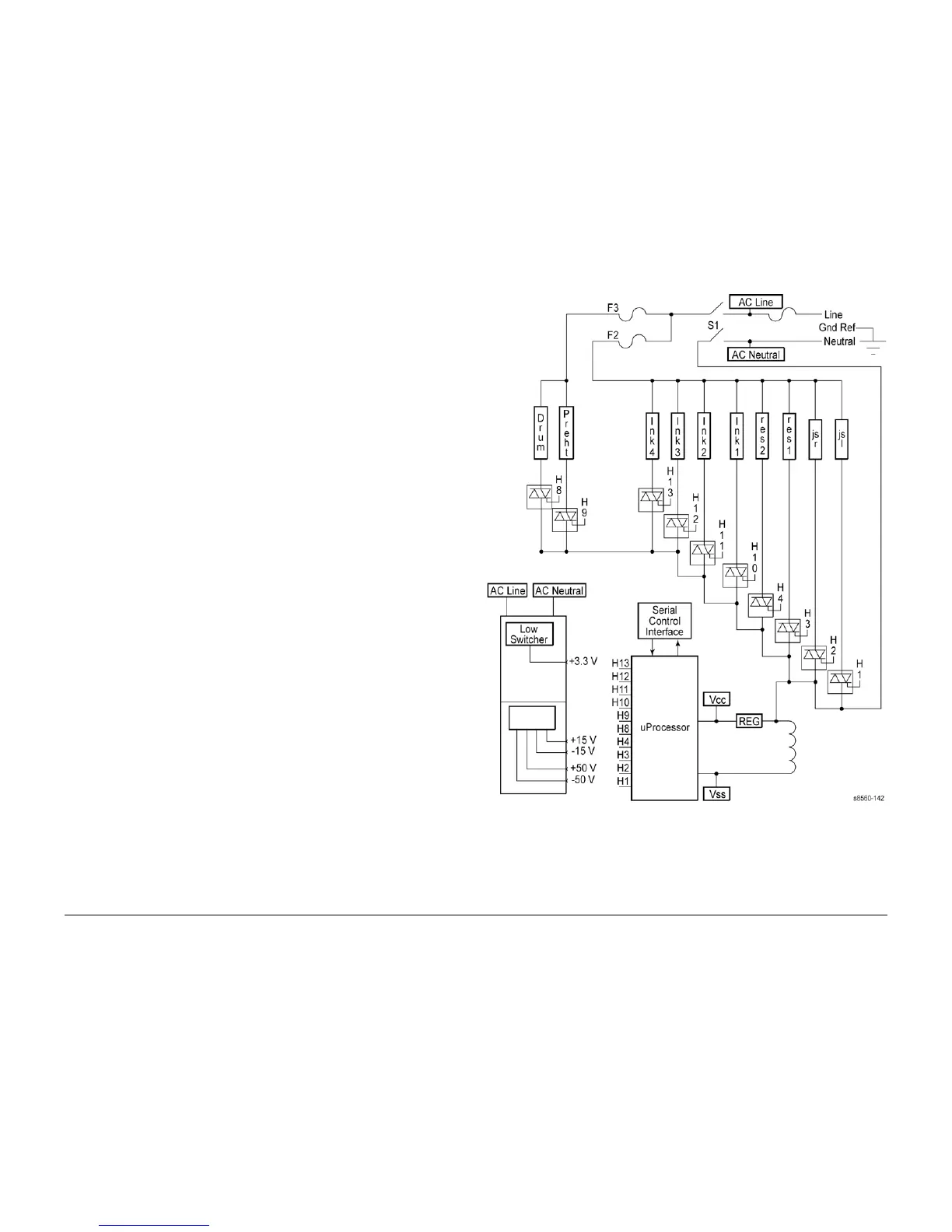
Figure 2 Power Supply Wiring Diagram
Hard Drive A Hard Drive IDE cable is plugged into the main board from the hard
drive board. A separate power cable must be plugged into the power con-
trol board from the Hard Drive board.
Flash Drive The Flash Drive is a solid state equivalent of the Hard Drive, but with
much smaller capacity (256 MB).
Configuration
Card
The Configuration Card is a thumbnail-sized device that plugs into the
side of the Electronics Module. This device stores system information
and interacts with NVRAM. When replacing the Electronics Module,
transfer the Configuration Card to the replacement Electronics Module.
Power Control
Board
The power control board distributes drive voltages to operate the sys-
tem’s various motors, solenoids and clutches. The power control board
also provides the interface that returns information from the system's sen-
sors to the main board. The sensors are used to track mechanical and
thermal functions, such as the position and temperature of the Printhead.
The power control board also generates regulated +/- 12 V and 5 V from
unregulated +/-15 V power.
Power Supply There are no field adjustments necessary on the power supply. In gen-
eral, the power supply has two main, yet interrelated sections: the AC
section and the DC section. In the AC section, power is routed to 10 tri-
acs. Under the main board logic control, the triacs supply AC power to the
10 heaters in the system.
Two fuses provide current protection to the triacs. Fuse F2 and F3 protect
the power supply from, most often, a shorted triac caused by a defective
heater. If the F2 or F3 fuses blow, it is best to replace the Electronics
Module (and, of course, the defective heater), rather than the fuse. Other-
wise uncontrolled, with the fuse replaced but the triac shorted, AC power
may be applied to the heater. Each time the main board turns on a triac to
activate a heater, it is turned on for only a fraction of a second. The main-
board must constantly readdress each heater it wants to remain on. This
means if the print engine firmware should fail, the heaters automatically
shut off.
The system is also protected by thermal fuses. A thermal fuse opens in
the unlikely event of a “runaway” heater following a hardware failure. The
drum and the Preheater thermal fuses are located on the Preheater.
Additional thermal fuses are located on the Printhead and on the ink
melting elements.
The DC power supply generates + 3.3 V, +/- 15 V, and +/- 50 V. These
voltages are used directly or regulated to other voltage values as needed
by various circuits in the system. The power control board regulates +/-
15 V to +/- 12 and other voltages. The main board also has regulators
providing + 5 V, + 2.5 V, and + 1.8 V. The power supply outputs + 3.3 V in
power saver mode. Fuse F1 provides protection for the switching power
supply in the DC section.
Electronics Module Components
 Loading...


