April 2017
8-57
Xerox® VersaLink® B7025/B7030/B7035 Multifunction Printer
Product Technical Overview
Launch Issue
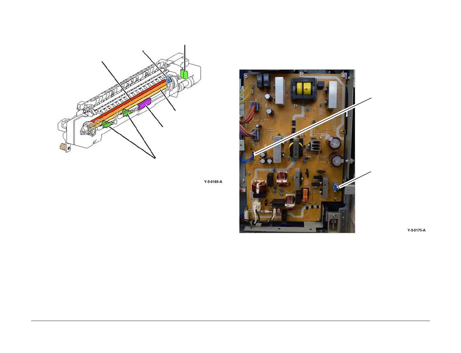
Figure 3 Fuser main components
Fuser Power
Main and sub heater on signal is supplied from P/J419 on the drive PWB, PL 1.10 Item 3 to P/
J504 on the LVPS, PL 1.10 Item 8. With the fuser relay energized, power is supplied from P2
on the LVPS, Figure 4, to the fuser power connector, Figure 5. Refer to BSD 10.1 Fusing Heat
Control (1 of 2).
The drive PWB controls fusing temperature as required by the temperature control logic.
Figure 4 Fuser power (LVPS)
Thermostats
Fuser NC sensor
Sub heater rod
Fuser PWB
Heat roll thermistor
Main heater rod
P2
P/J504
 Loading...