Engine control unit and component
5-18
Using the digital tester
The electrical technical data applies to the
measurements taken using the Yamaha rec-
ommended tester.
The resistance values shown are the values
taken
before the engine is started. The actual
resistance may vary depending on the environ-
mental conditions and ambient temperature.
The input voltage changes depending on the
battery voltage
. Check the battery and wire
harness if the input voltage is less than the
specified value. Check the components be-
tween the battery and the input voltage mea-
suring point if there is no problem with the
battery and wire harness.
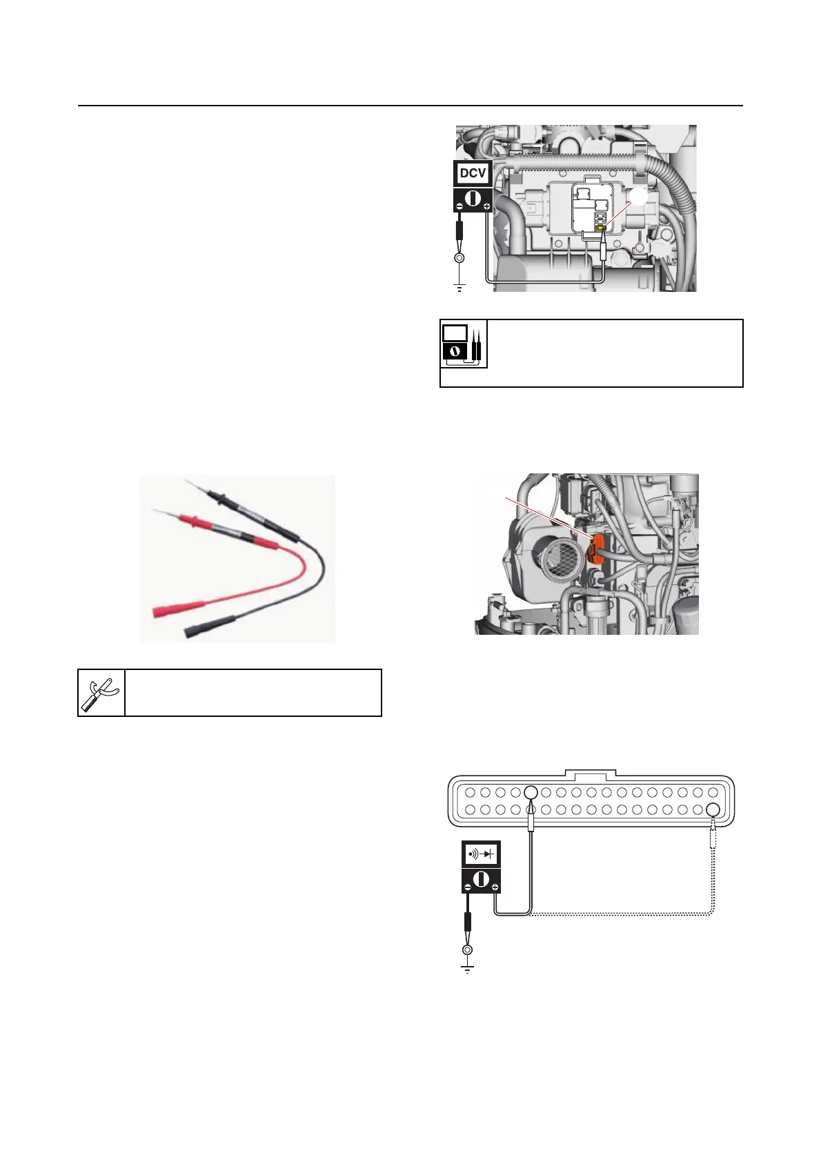
If the tester probe cannot be inserted into the
coupler,
prepare a test lead suitable for the
measurement.
Engine control unit and compo-
nent
Checking the main relay
The main relay cannot be removed for testing
or replaced as a single unit because it is a com-
ponent part of the fuse box. See “Fuse box”
(2-11).
1. Check:
• Trouble code on the YDIS
See “Troubleshooting procedure” (4-4).
2. Measure:
• Main fuse input voltage
Out of specification See “Troubleshoot-
ing the power unit” (4-8).
Checking the engine ECM circuit
1. Disconnect:
• Engine ECM coupler “a”
2. Check:
• Engine ECM ground circuit continuity
Out of specification Replace the wire
harness.
Tester leads
90890-06881
Main fuse input voltage
12 V
Main fuse “a”–Ground
a
a