Engine control unit and component
5-19
3. Measure:
• Engine ECM input voltage
Out of specification Check the wire har-
ness for continuity.
a. Turn the engine start switch to ON,
and then measu
re the input voltage at
the engine ECM coupler terminal and
ground.
b. Turn the engine start switch to OFF.
4. Connect:
• Engine ECM coupler
Checking the TPS
1. Measure:
• TPS output voltage
Out of specification Check the TPS in-
put voltage.
a. Connect the YDIS to display “TPS
voltage”.
b. Start the engine and warm it up for 5–
10 minutes, and then stop it.
c. Turn the engine start switch to ON,
and then measure the TPS
output
voltage when the remote control lever
is at the fully closed position.
d. Turn the engine start switch to OFF.
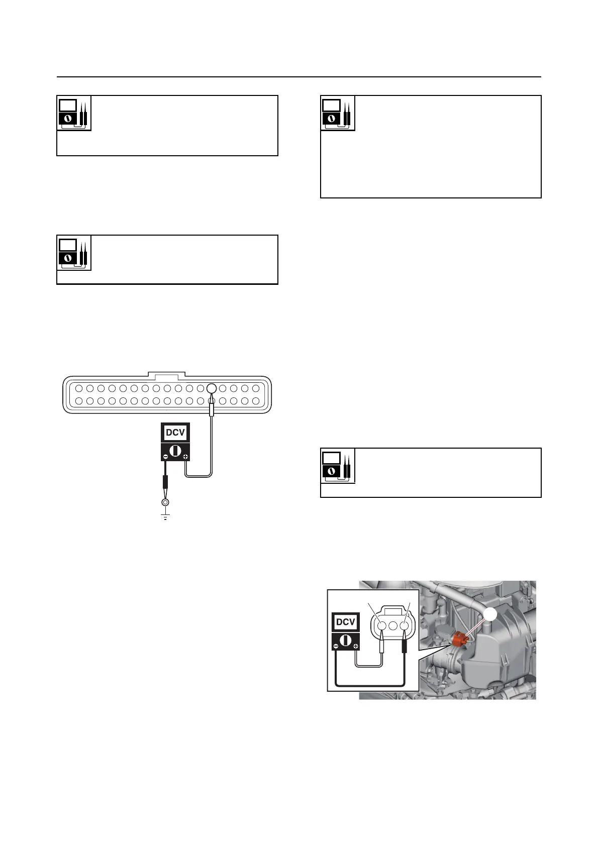
2. Measure:
• TPS input voltage
Out of specification Check the
wire har-
ness for continuity.
a. Disconnect the TPS coupler “a”.
b. Turn the engine start switch to ON,
and
then measure the TPS input volt-
age at the TPS coupler.
c. Turn the engine start switch to OFF.
d. Connect the TPS coupler.
Engine ECM ground circuit continu-
ity
Terminal 5–Ground
Terminal 34–Ground
Engine ECM input voltage
12 V
Terminal 13–Ground
Output voltage at throttle valve fully
closed
0.58 V
Throttle valve opening angle at
throttle
valve fully closed (reference
data)
0.0
Input voltage
5 V
Orange (Or)–Black (B)
a
BOr