Engine control unit and component
5-21
c. Apply positive pressure to the oil pres-
sure switch “1” slowly, and then check
that continuity is lost in the range of the
working pressure.
d. Disconnect the special service tool.
e. Install the oil pressure switch. See
“Cylinder block” (7-42).
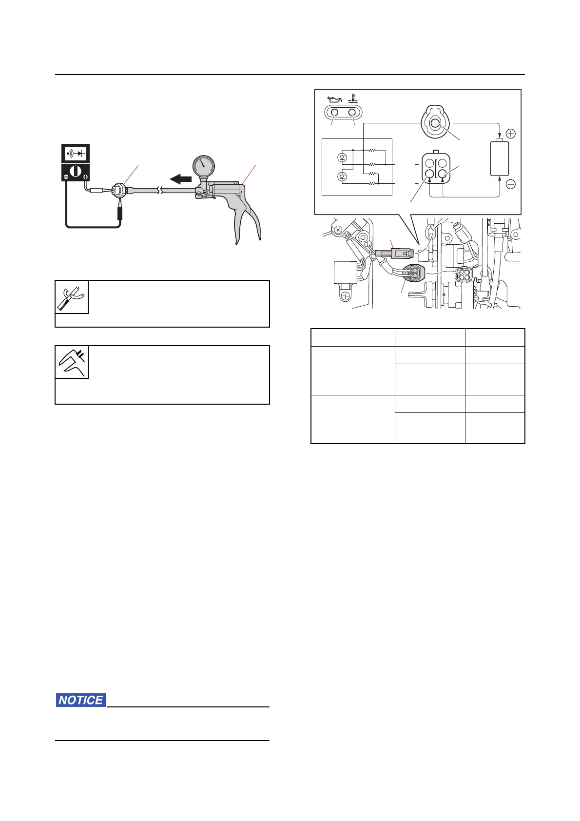
Checking the alert indicator (tiller han-
dle model)
1. Check:
• Ale
rt indicator continuity
Out of specification Replace.
a. Remove the tiller handle cover, and
then disconnect
the alert indicator
couplers “a” and “b”.
b. Connect the battery (1.5 V) to the alert
indicator couplers
“a” and “b”. Check
that the overheat alert indicator “c” or
the oil pressure alert indicator “d”
comes on. Replace the alert indicator
if it does not come on.
Do not apply a voltage higher than 1.7 V
when checking the LED.
c. Connect the alert indicator couplers
and, and then install the tiller handle
cover.
Checking the alert buzzer
1. Check:
• Alert buzzer continuity
Out of specification Replace.
a. Remove the alert buzzer.
Vacuum/pressure pump gauge set
“2
”
90890-06945
Oil pressure switch
Working pressure
127.50–166.70 kPa (1.275–1.667
kgf/cm², 18.49–24.17 psi)
1
2
Lighting-up Terminal Battery
Overheat alert
indicator “c”
Yellow (Y) (+)
Pink/Black
(P/
B)
(–)
Oil pressure
a
lert indicator
“d”
Yellow (Y) (+)
Pink/White
(P/W)
(–)
a
b
a
b
P/W
P/W
P/B
P/B
d
d
c
c
Y