Fuel control unit and component
5-22
b. Connect the battery leads to the alert
buzzer connectors, and check that the
alert buzzer comes on. Replace the
alert buzzer if it does not come on.
c. Install the alert buzzer.
Fuel control unit and component
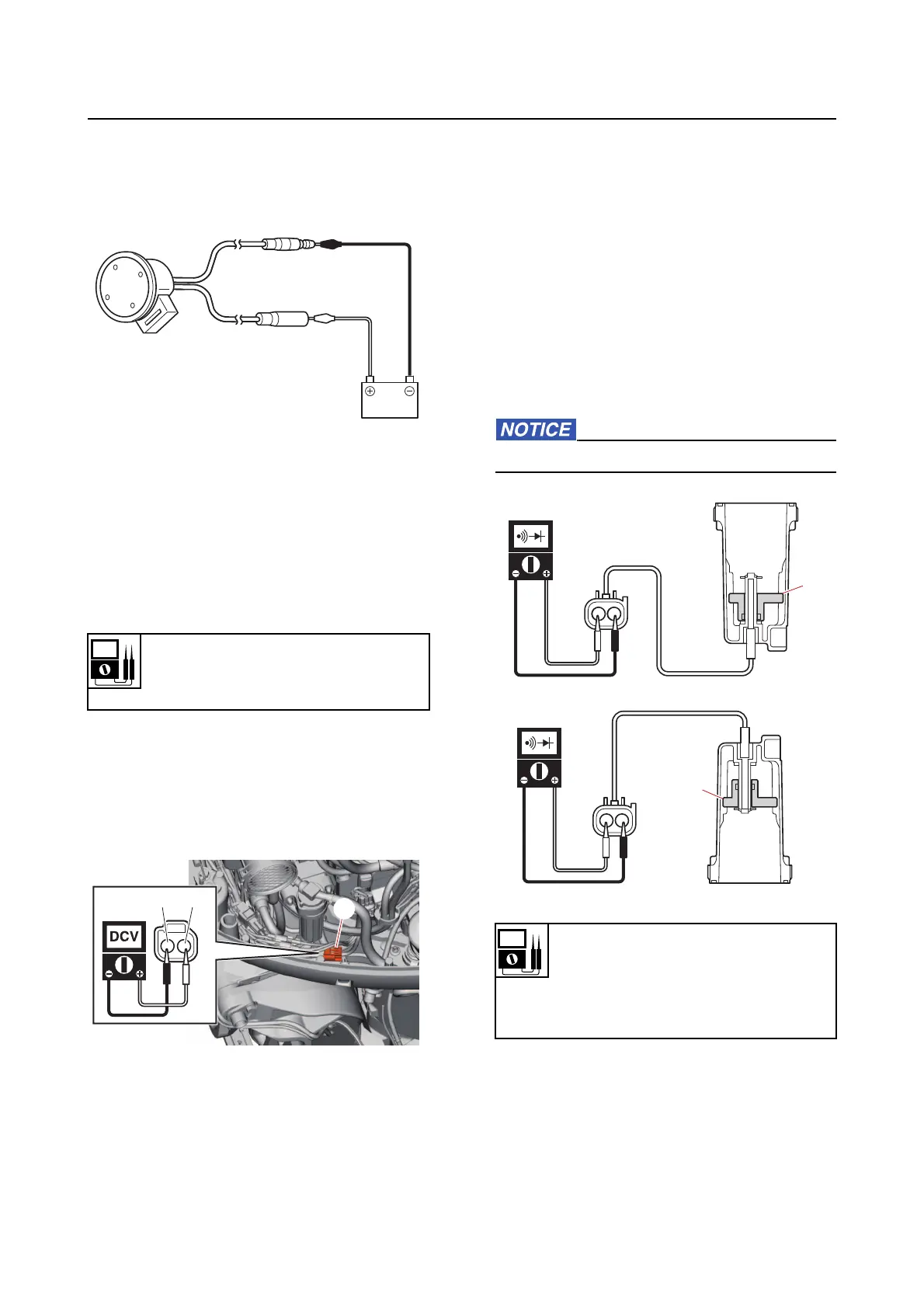
Checking the water detection switch
1. Measure:
• Water detection switch input voltage
Out of specification Check the wire har-
ness for continuity.
a. Disconnect the water detection switch
coupler “a”.
b. Turn the engine start switch to ON,
and then measu
re the input voltage at
the water detection switch coupler.
c. Turn the engine start switch to OFF.
d. Connect the water detection switch
coupler.
2. Check:
• Water detection
switch continuity
Out of specification Replace the fuel
cup assembly.
a. Remove the fuel cup assembly. See
“Fuel filter” (6-4).
b. Check that the float “1” moves
smoothly
.
c. Check the water detection switch for
continuity
when the float “1” is in posi-
tions “A” and “B”.
Do not remove the clip and float.
d. Install the fuel cup assembly. See “Fu-
el filter” (6-4).
Input voltage
12 V
Blue/White (L/W)–Black (B)
a
L/W
B
Water detection switch continuity
No continuity
Float position “A”
Continuity
Float position “B”
1
A
1
B