PTT system
5-41
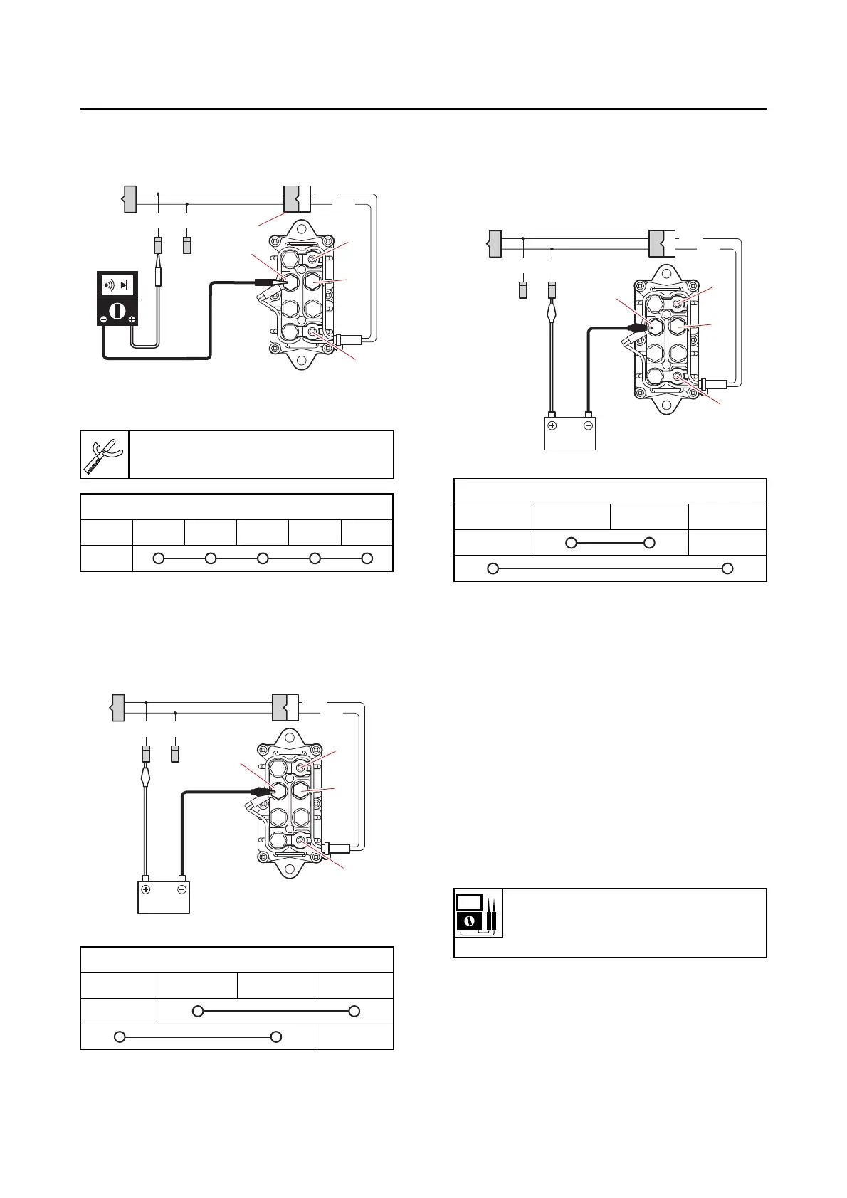
d. Check the PTT relay for continuity.
e. Connect the positive battery lead to
the terminal “a”, and the negative bat-
tery lead to the terminal “b”, and then
check the PTT relay for continuity.
f. Connect the positive battery lead to
the terminal “a”, and the negative bat-
tery lead to the terminal “b”, and then
check
the PTT relay for continuity.
g. Disconnect the special service tool.
h. Install the PTT relay.
i. Connect the PTT relay coupler, bat-
tery power source, ground lead, and
PTT motor leads.
Checking the PTT switch (on bottom
cowling)
1. Measure:
• PTT switch input vo
ltage
Out of specification Check the
wire har-
ness for continuity.
a. Disconnect the PTT switch coupler
“a
”.
Test harness FWY–2 “1”
90890-06917
PTT relay continuity
“a” “b” “c” “d” “e” “f”
PTT relay continuity
“b” “c” “d” “e”
G/W
G
Lg
Sb
1
e
f
d
c
a
b
PTT relay continuity
“b” “c” “d” “e”
Input voltage
12 V
Red (R)–Ground
G/W
G
Lg
Sb
a
e
d
c
b