PTT system
5-42
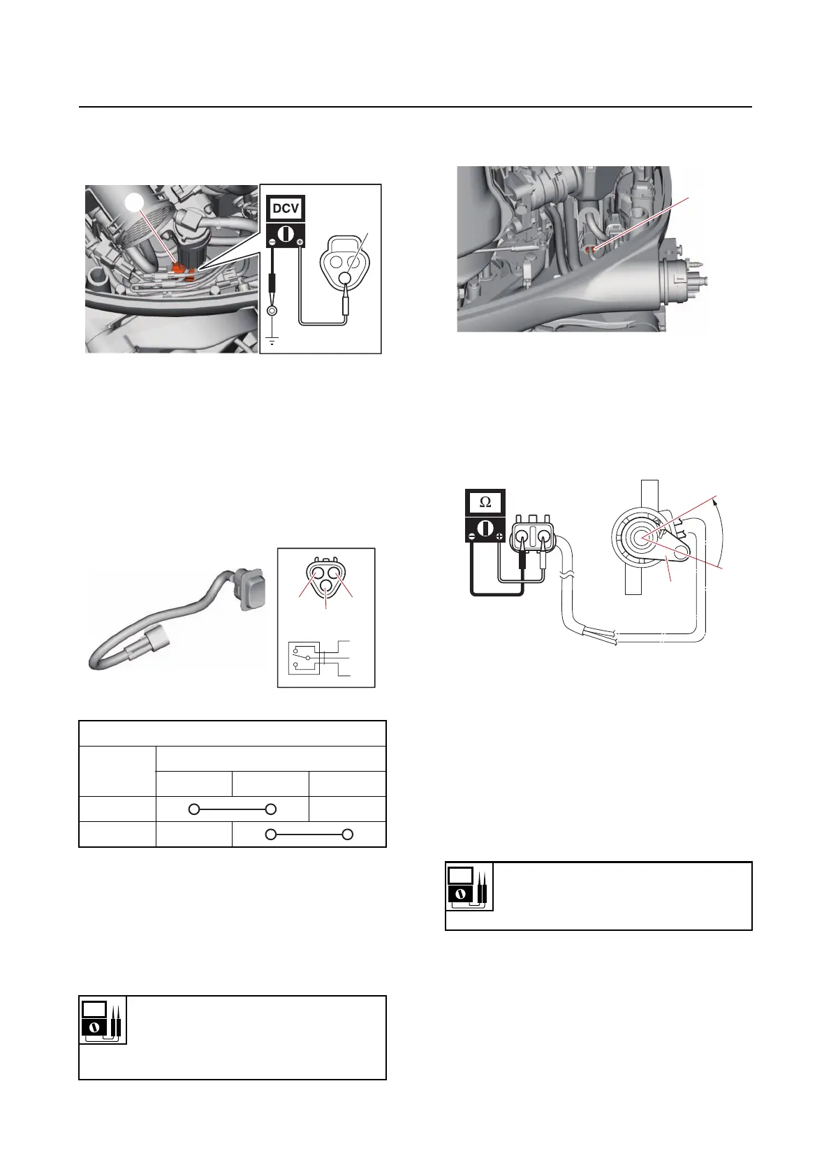
b. Measure the input voltage between
the PTT switch coupler terminal and
ground.
c. Connect the PTT switch coupler.
2. Check:
• PTT switch continuity
Out of specification Replace.
a. Disconnect the PTT switch coupler.
b. Check the PTT switch for continuity.
c. Connect the PTT switch coupler.
Checking the trim sensor
1. Measure:
• Trim sensor resistance
Out of specification Replace.
a. Disconnect the trim sensor coupler
“a
”, and then remove the trim sensor.
b. Measure the trim sensor resistance.
c. Turn the trim sensor lever “1” from the
free position “a” to
the setting position
“b”, and then measure the resistance
as it gradually changes.
d. Install the trim sensor, and then con-
nect the trim sensor coupler.
Checking the tilt limiter (remote con-
trol model)
1. Measure:
• Tilt limiter input vo
ltage
Out of specification Check the
wire har-
ness for continuity.
a. Disconnect the tilt limiter couplers “a”,
“b
”, and “c”.
PTT switch continuity
Switch
position
Te r mi na l
“a” “b” “c”
UP
DN
Free position resistance
239–379
Setting resistance
9–11
R
a
Input voltage
12 V
Sky blue (Sb)–Ground
a
1
a
b