PTT system
5-43
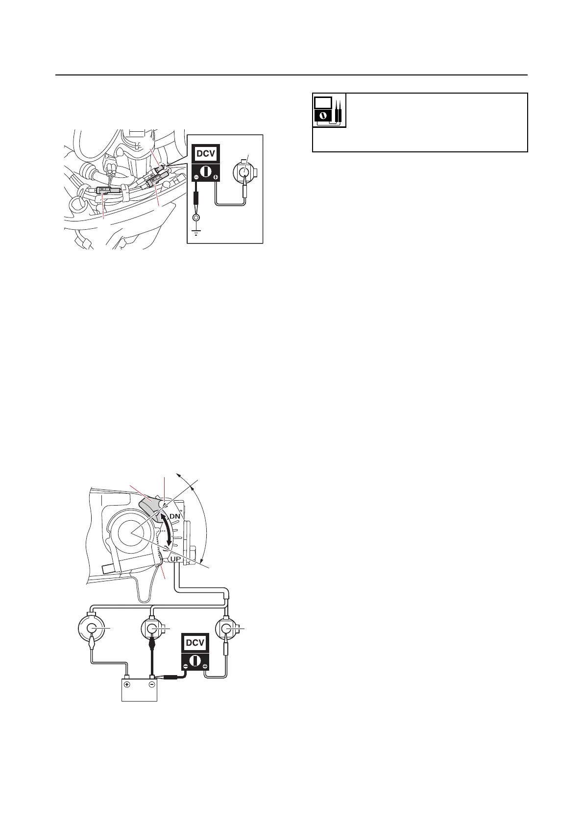
b. Measure the input voltage at the tilt
limiter coupler “a” with the up side of
the PTT switch pushed.
c. Connect the tilt limiter couplers.
2. Measure:
• Tilt limiter output vo
ltage
Out of specification Replace.
a. Disconnect the tilt limiter couplers.
b. Connect the battery leads to the tilt
limiter couplers.
c. Loosen the screw “1”, and measure
the output voltage at range “a”. Slide
the
magnet “2” to mark “b”. When the
magnet passes mark “b”, measure the
output voltage again.
d. Connect the tilt limiter couplers.
e. Set the tilt limiter.
Sb
a
b
c
LB
Sb
a
b
2
1
Output voltage
12 V at “a”
0 V when passing “b”
Blue (L)–Ground