Power unit (check and adjustment)
7-3
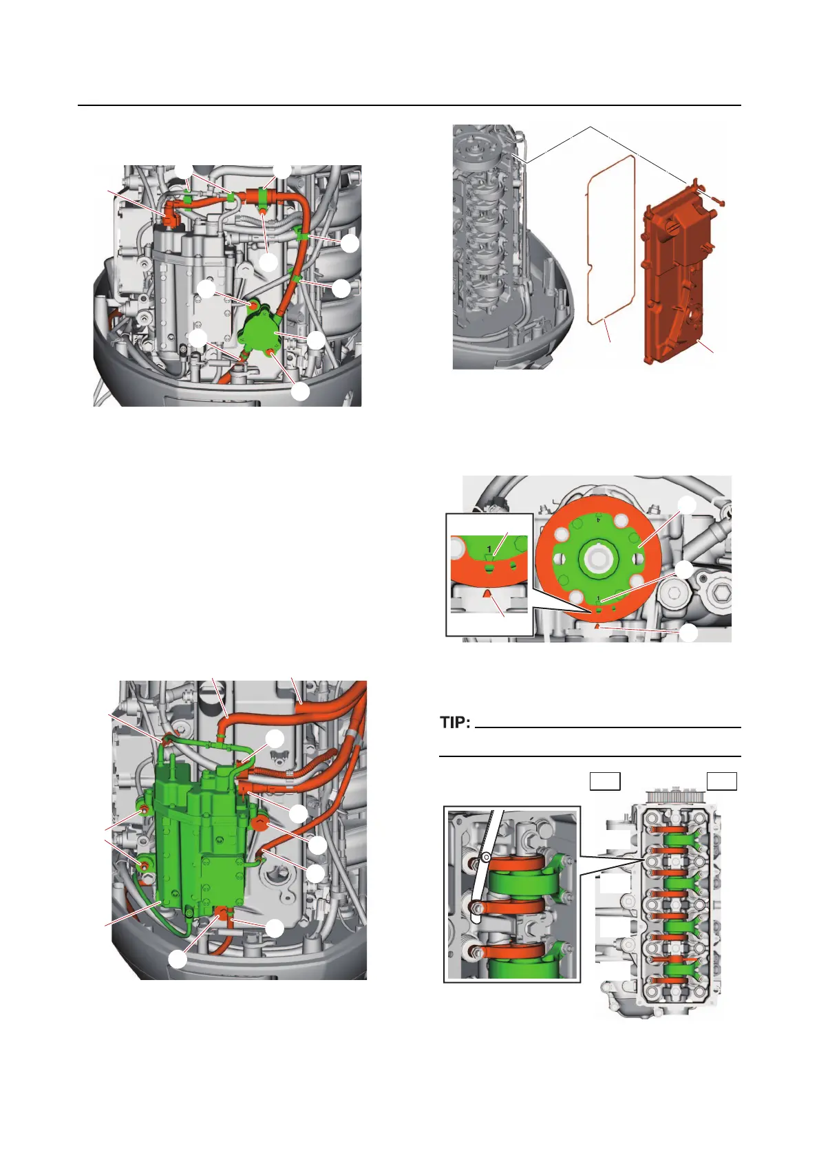
f. Remove the fuel pump bolts “8”, fuel
pump assembly “9”, and O-ring.
g. Remove the clamp “1”.
h. Disconnect the high-pressure fuel
pump
coupler “a” and quick connector
“2”. See “Disconnecting the quick con-
nector” (6-1).
i. Disconnect the hoses “3”, “4”, “5”, and
“6”.
j. Remove the vapor separator bolts “7”
and nuts “8” and vapor separator “9”.
k. Remove the cylinder head cover “1”
and gasket “2”.
l. Turn the flywheel magneto clockwise
to align
the “1 △ ” mark “a” on the driv-
en sprocket “1” with the “ △ ” mark “b”
on the cylinder head.
m. Measure the valve clearances “a” and
“
b” according to steps (n)–(p).
Write down the measurement data.
6
3
2
1
4
5
7
8
9
8
3
4
2
a
5
6
1
8
7
7
9
2
1
b
1
a
b
a
#1
#2
#3
#4
EX
IN