Power unit (check and adjustment)
7-4
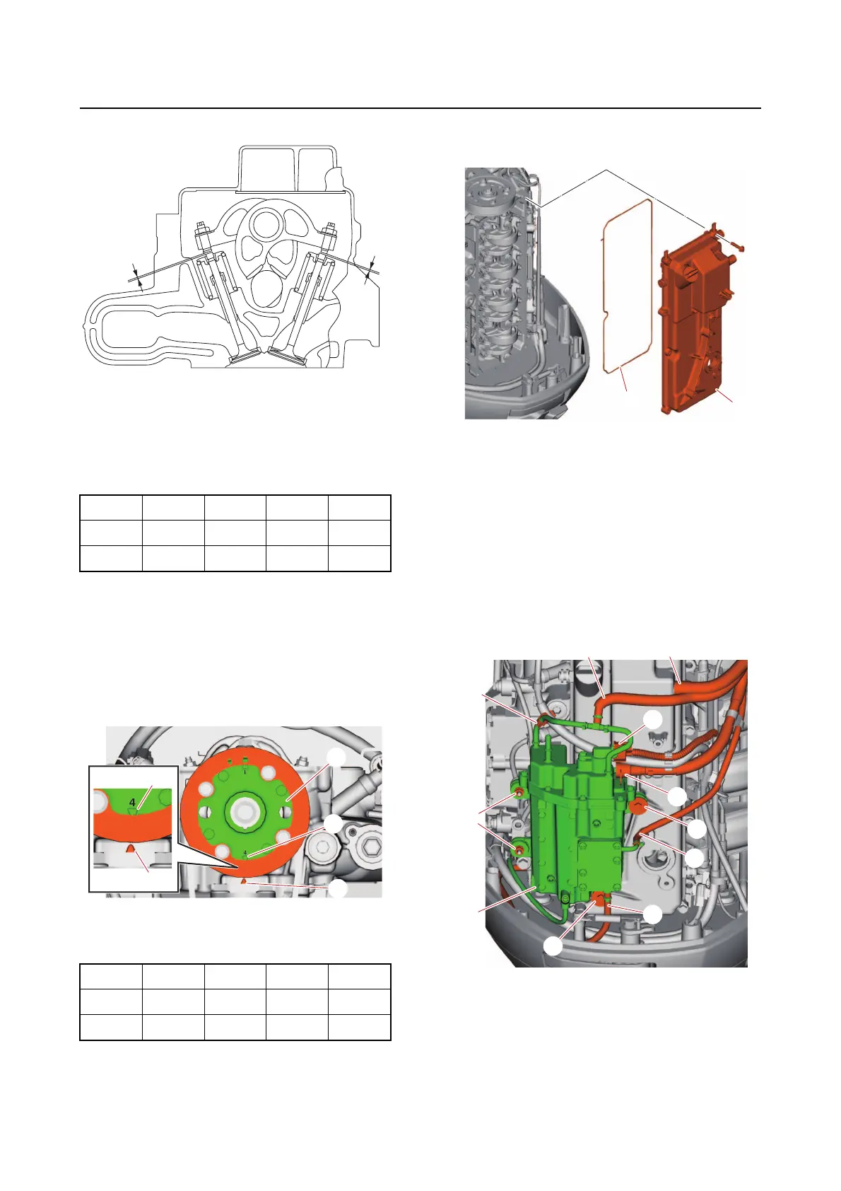
n. Measure the intake and exhaust valve
clearances of the specified cylinders.
—: Not applicable
: Specified cylinder
o. Turn the flywheel magneto clockwise
360 to
align the “4 △ ” mark “a” on the
driven sprocket “1” with the “ △ ” mark
“b” on the cylinder head.
p. Measure the intake and exhaust valve
clearances of the applicable cylinders.
—: Not applicable
: Specified cylinder
q. Install a new gasket “2” and the cylin-
der head cover “1”.
r. Install the vapor separator “9” and va-
por separator nuts “8” and bolts “7”.
s. Connect the hoses “3”, “4”, “5”, and
“6
”.
t. Connect the high-pressure fuel pump
coupler “a” and quick connector “2”.
u. Install the clamp “1”.
v. Install a new O-ring to the fuel pump
assembly, and
then install the fuel
pump assembly to the cylinder head
cover. See “Installing the fuel pump
assembly” (6-12).
a. Intake
b. Exhaust
#1 #2 #3 #4
IN — —
EX — —
#1 #2 #3 #4
IN — —
EX — —
a
b
b
1
a
b
a
2
1
3
4
2
a
5
6
1
8
7
7
9