Camshaft and valve
7-40
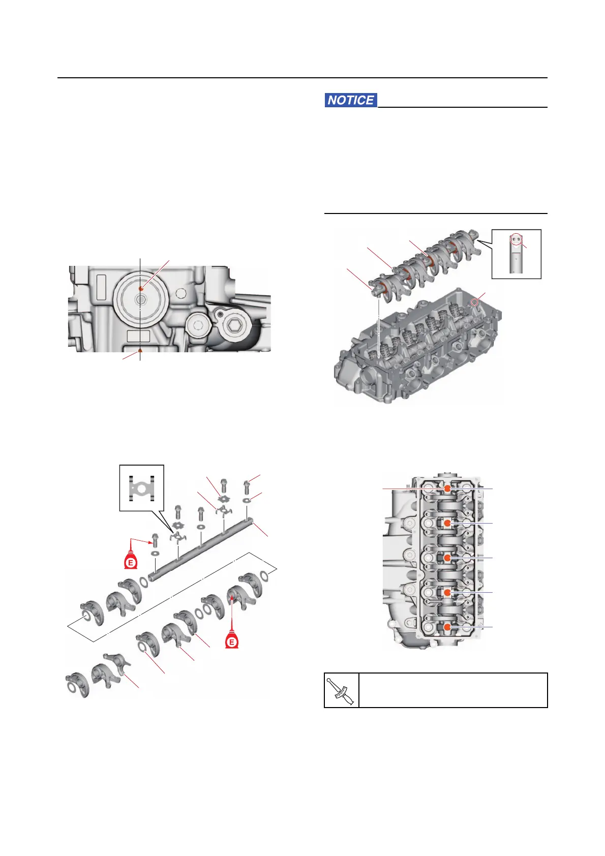
5. Install:
• Rocker arm
• Washer
• Rocker arm shaft
• Tensioner
• Stopper
• Washer
• Rocker arm shaft bolt
a. Align the dowel hole “a” in the cam-
shaft with the “ △ ” mark
“b” on the cyl-
inder head.
b. Assemble the rocker arms “1”, “2”, and
“3”,
washers “4” onto the rocker arm
shaft “5”, and then install the tension-
ers “6”, stoppers “7”, washers “8”, and
rocker arm shaft bolts “9”.
c. Install the rocker arms “1” and rocker
arm shaft “2” as an assembly.
• Be careful not to damage the washers “3”
when installing the rocker arm shaft as-
sembly to the cylinder head.
• Make sure to install the rocker arm shaft
in the correct
direction aligning its oil
holes “a” with the oil holes “b” in the cyl-
inder head.
d. Tighten the rocker arm shaft bolts “1”
gradually to the specified torque and in
the order [1], [2], and so on.
6. Install:
• Cylinder he
ad
See “Installing the cylinder head” (7-28).
b
a
1
2
3
4
5
6
7
8
9
Rocker arm shaft bolt “1”
28 N·m (2.8 kgf·m, 21 lb·ft)
1
b
a
2
3
1
[2]
[4]
[1]
[5]
[3]