Electrical component (tiller handle)
9-8
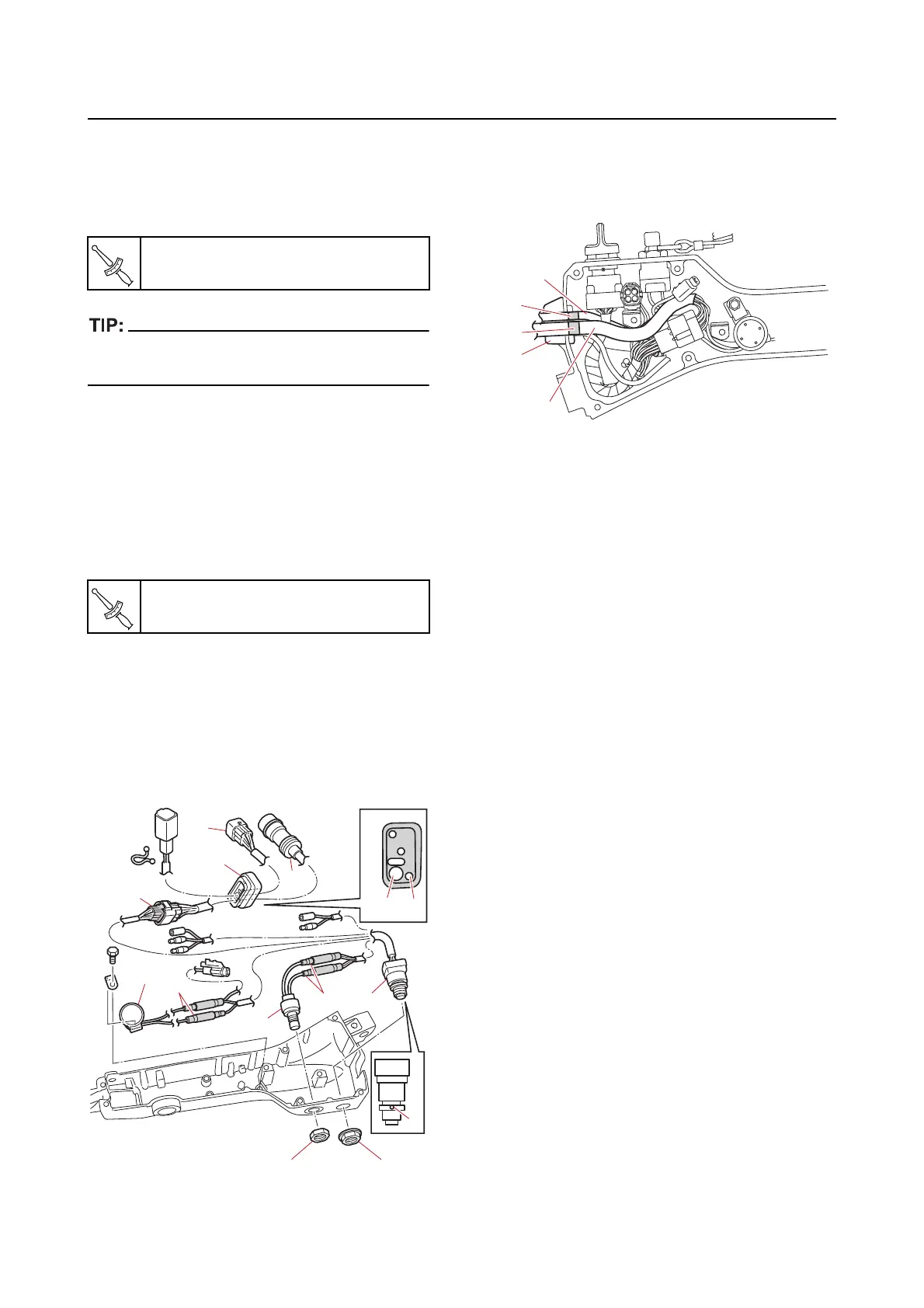
Assembling the electrical component
1. Install:
• Engine start
switch “1”
• Engine start
switch nut “2”
Install the engine start switch “1” so that the
hole “a” is facing up.
2. Pass the extension wire harness “3” and
alert indicator harness “4” through the
grommet “5”, and then install them.
3. Install:
• Engine shut-off switch “6
”
• Engine shut-off switch nut “7”
4. Install:
• Buz
zer “8”
5. Connect:
• Engine shut-off switch connector “b”
• Buzzer connector “c”
• Engine start
switch coupler “d”
6. Align the blue tape “a” on the extension
wire harness “1”
and green tape “b” on the
alert indicator harness “2” with the inner
end of the grommet “3”.
Engine start switch nut “2”
4.4 N·m (0.44 kgf·m, 3.2 lb·ft)
Engine shut-off switch nut “7”
2.3 N·m (0.23 kgf·m, 1.7 lb·ft)